
DIY MFOS Voltage Controlled Oscillator KB
We always recommend visiting the MFOS website before building where the latest 'offical' information and news can be found. Here on the Soundtronics website, you will find selected information from the MFOS site plus additional information and resources to aid the building and maintaining of your MFOS synth.
Introduction to the MFOS VCO
The heart of the synth is the tone generators and the MFOS VCO is an excellent example of a traditional oscillator with an excellent performance specification if you take care with component selection but more on that later. Visit the MFOS website for MP3 samples
Features
- Years of MFOS VCO improvements all rolled into this design.
- Good tracking over several octaves (6 to 8).
- Can be temperature compensated with a metal film 2K Ohm 1/4W +/-2% T.C. +3300 PPM tempco.
- Simultaneous Rectangle, Ramp, Triangle and Sine Outputs (Ramp core design)
- Designed for 1V/Octave control voltage
- 4 1V/Octave control voltage inputs.
- 1 Linear control voltage input.
- Hard sync input.
- Rectangle wave duty cycle adjustable between 10% and 90%
- Rectangle wave duty cycle voltage controllable
- Frequency range is from sub audible (approximately 0.1 hertz) to ultra-sonic 20kHz.
- Power supply can be +/-12 or +/-15 volts.
Documentation & Downloads
- MFOS Original Build Documentation (We have taken the MFOS VCO webpage and converted it to a PDF document for easy reading and printing out)
- Schematic Page 1
- Schematic Page 2
Building Guide
The VCO module has been rated by MFOS as an Intermediate to Advanced project and not recommended for beginners. To get the best performance from this module, having suitable test equipment is assumed in order to calibrate the VCO. Two main issues that affect VCOs, temperature stability and tracking. This design addresses both of these issues assuming appropriate selection of components.
Assembly instructions for this module can be found under the 'Build Guide' tab on the parts kit page
Calibration
Ideally you have access to an accurate voltmeter or standard voltage source, frequency meter and an oscilloscope. You can get by with less but we will describe how we calibrate a VCO using this test gear. Sorry about the quality of the pics, they were taken with a mobile phone as the screen capture software would not work with Windows 7 and tme to dot permit us finding out why.
There are 7 presets used for calibrating the VCO ideally adjusted in this order:
- R5 - Ramp Offset Bias
- R7 - Traingle Offset Bias
- R60 - Sine Wave Bias
- R64 - Sine Wave Shape
- R59 - Sine Wave Level
- R16 - 1V/Octave Scale Trim
- R11 - High Freq Compensation Trim
Starting with R5:
With an oscilloscope, monitor the wavform at the output U4-A (pin 1 of the TL074) and adjust R5 until the waveform has equal positive and negative excusions around the 0V line. If your scope has a measure function using cursors or even displays the excursions as values, all the better. It does not have to be absolutely precise at this stage as any error will show up in the next step.
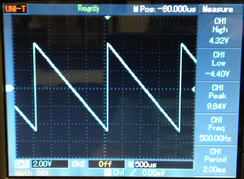
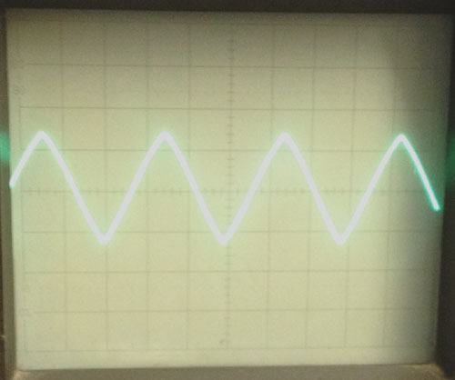
Connect your scope to the triangle wave output socket and you should see:
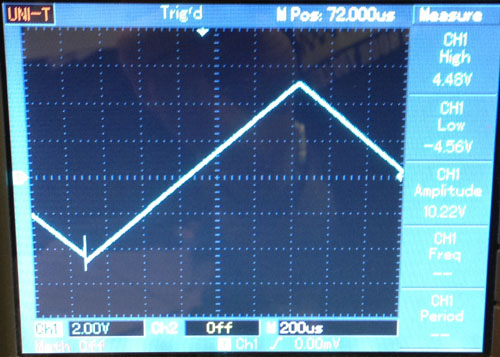
If R5 is not set correctly, you will see an offset in the falling and rising ramps of the triangle waveform. Tweak R5 so they meet at the negative peak. Then use R7 to adjust the position of the waveform so that it equally biased around the 0V level.
Next is the sine wave using R60, R64 and R59
This is described in detail on the MFOS site which you can also view here using this PDF MFOS Original Build Documentation
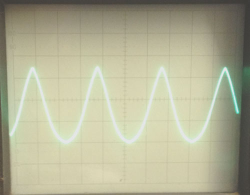
We have found there is a slight point at the peaks of the sine wave which we did not manage to eliminate without adversely affecting the sine shape too much.
Start with R60 and adjust until the top half of the sine wave form looks to be the same as the bottom half.
Not like this
or this
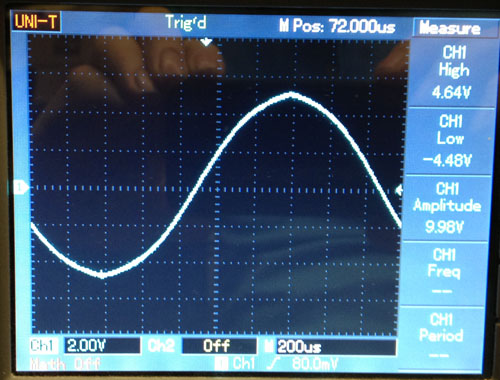
but this
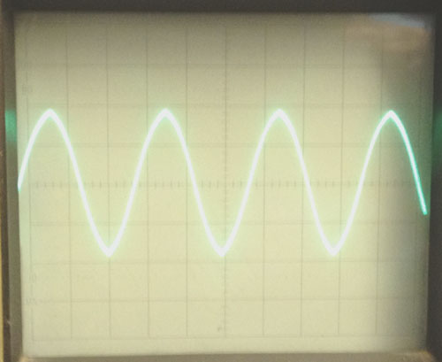
Now use R64 to adjust the shape of the sine wave. If you have a harmonic analayser then that may well aid the tuning although with a scope and a good ear you can get equally good results.
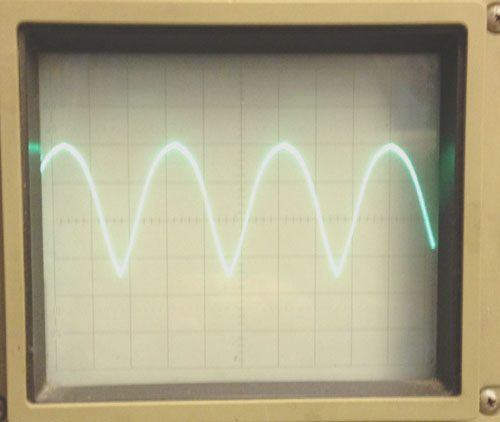
We all know what a sine wave looks like
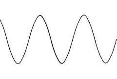
Well, the image below is simply too rounded at the peaks and on its way to becoming a square wave.
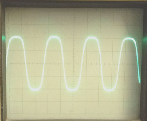
Adjust too far the other way and you are getting back to a triangle wave
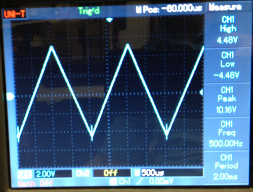
Back to the digital scope again and this was the best we could get
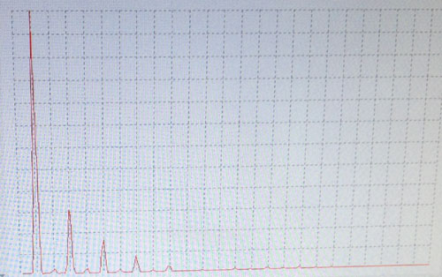
If your scope has a FFT function you can display the harmonics and of course for a sine wave you ideally only want to see a single peak at the fundamental frequency. Here is a capture from our SynthScope before tuning the wave shape and you can see the additional peaks from other harmonics present.
The final step in the calibration process is the voltage / frequency tracking. We are looking for a 1V/octave relationship and the closer we can get it over 7 octaves the better your tuning will be (especially useful if you use multiple oscialltors for that fat sound). We use a voltage calibrator that we made largely based on a design from MFOS. This speeds up the process in that you can quickly go from one voltage to another without continually which you need to do when calibrating. You can use other voltage sources such as a MIDI to CV converter but you need to be satisfied that its accuracy is sufficient. We are achieving better than 0.02% accuracy from our calibrator with an aim of getting better than 0.1% tracking error from the VCO.
First set R16 so that it is in the middle (12.5 turns) and R11 fully counter clockwise.
Step 1
With your voltage calibration source connected to the raw CV input (the other two FM inputs have a FM pot on their signals) and set to 0V, use the coarse and fine controls to give an output frequency as measured on a frequency meter of 27.5Hz, the fine control is still rather coarse for fine tuning to the third decimal place but can be done. You can start with 25Hz if you prefer but remember that each 1V increase doubles the preceeding frequency so you will be looking for 25, 50, 100, 200, 400, 800, 1600, 3200Hz. Our results are based on 27.5Hz as a starting point as it covers key 1 to key 85 on a piano so we are looking for 27.5, 55, 110, 220, 440, 880, 1760, 3520Hz.
Step 2
So, with an output frequency of 27.500Hz, set the CV to 3V and you should get 220Hz. If not (most likely), you need to adjust R16. The way in which R16 is adjusted may appear odd at first but following this method may help:
If the frequency at 3V is lower (flat) than 220Hz, then adjust R16 to make the frequency even flatter by about the same amount it is flat by. For example, if the frequency at 3V is 212Hz, then use R16 to make the frequency 204Hz. If it is high (sharp) then adjust R16 to make the frequency even sharper by about the same amount it is sharp by. For example, if the frequency at 3V is 226Hz, then use R16 to make the frequency 232Hz. Go back to step 1 until you get 220Hz at 3V.
Step 3
Now set the CV to 7V, you should get 3520.00Hz, if not as it is most likely flat, then adjust R11 to bring the frequency up to 3520Hz.
You can repeat the above process to to make sure the low end is still fine, patience will bring in some rather good results. We have build oscillators using both matched discrete transistors and the SSM2212 and we have found best results from the SSM2212 which we now adopt for all builds.
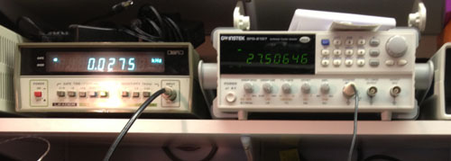
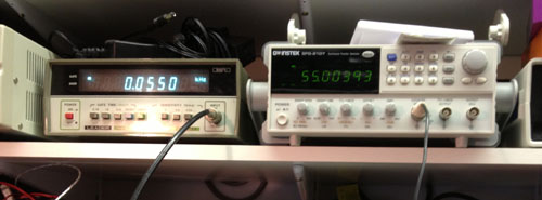
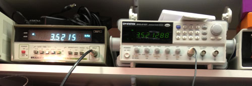
It is also worth running the oscillator at all voltages to see how well it tracks across all 7 octaves. We used two frequency meters, the left hand meter is a counter with a 10 second gate time, the right hand meter actually measures the average pulse width and gives quick readings and to a better resolution.
At 0V it should be 27.5Hz
at 1V it should be 55Hz
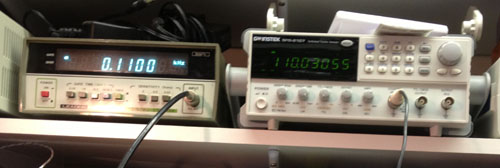
At 2V it should be 110Hz
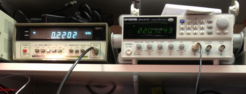
At 3V it should be 220Hz
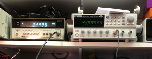
At 4V it should be 440Hz
At 5V it should be 880Hz
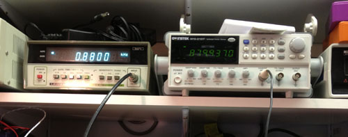
At 6V it should be 1760Hz
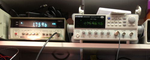
and at 7V it should be 3520Hz
Results in tabulated form
| Input Voltage | Desired Frequency | Actual Frequency Hz | Error Hz | Error (% of reading) |
| 0 | 27.5 | 27.50646 | 0.00646 | +0.02349% |
| 1 | 55 | 55.00393 | 0.00393 | +0.00714% |
| 2 | 110 | 110.0306 | 0.0306 | +0.02781% |
| 3 | 220 | 220.1243 | 0.1243 | +0.0565% |
| 4 | 440 | 439.9494 | -0.0506 | -0.0115% |
| 5 | 880 | 879.937 | -0.063 | -0.00715% |
| 6 | 1760 | 1759.646 | -0.354 | 0.02011% |
| 7 | 3520 | 3521.288 | 1.288 | 0.03659% |
The greatest error of 0.03659% is well inside our target of 0.1% over 7 octaves.
That completes the VCO calibration.