
MFOS Transistor Matching
10 Feb 2014
A number of the MFOS synth modules require matched pairs of NPN and PNP transistors. Ray Wilson at MFOS has published a number of circuits for matching transistors. We have taken those circuits and modified them slightly to derive our own in-house transistor matcher.
The aim is to produce matched pairs where the Vbe is within 1.5mV of each other (revised to 0.7mV as of July 2014, see update below). The main issue being their temperature dependence where the Vbe can change by around 2mV per Deg C of temperature change. Our problem is that the temperature in our workshop simply varies far more than that due to the electric heating and it being mid-winter at the time of writing.
So how does our design differ from Ray's? First thing we like to do is not trust on zener diodes for voltage references due to their 680ppm / DegC drift so we replaced that with a 10V high stability reference chip. Secondly, we built both of the NPN and PNP transistor circuits and used a selector switch to select the polarity required. Rather than have a single test socket, we used 12 sockets with a selector switch to check each transistor in turn thus minimising the handling. Finally, we used a heater pad with a temperature control circuit to heat the test box internals to 30 Deg C.
We have found that we were able to match transistors to better than 1mV, in fact we aim to not select pairs over 0.7mV apart (see update below). The transistor pairs are available to purchase from soundtronics if you do not wish to have the trouble of matching yourself.
![]()
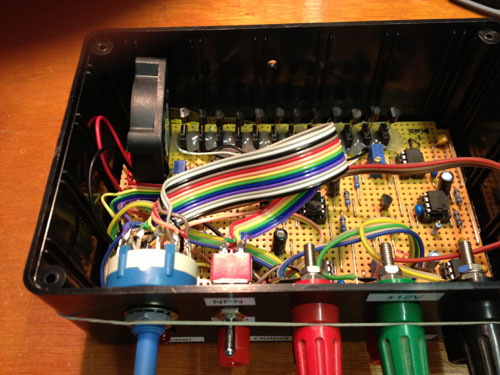
The following pic shows the internals, note the 12 off test sockets.
![]()
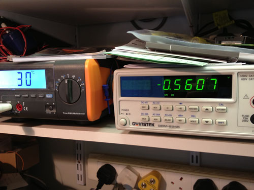
Finally this pic shows the temperature controlled heat pad used to maintain the internal temperature to better than 0.4 Deg C
![]()
Update July 4th 2014
We have been optimising the temperature control and are now achieving really good stability so we can now match transistors even more closely than before.
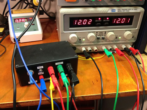
The pic below shows twelve 2N3904 transistors inserted into the test sockets.
Now the tester is plugged into the +/- 12V and +5V supplies, the output connected to the high resolution digital voltmeter and a temperature probe purely to monitor the temperature inside the tester.
The temperature is allowed to heat up to 30 Deg C and with transistor 1 junction voltage drift being monitored until it stabilises to within 0.2mV. This takes about twenty minutes typically.
In this case, transistor 1 stabilised at 560.7mV. Each transistor was elected in turn using the rotary switch and a note of each voltage reading taken. Then each reading was taken again and compared to that written down to ensure all readings were the same +/- 0.1mV in case of human error in writing the figures down or there has been further drift.
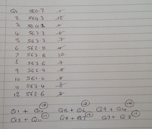
Now each voltage reading has been recorded, they are numbered in ascending order and pairs selected that are within 0.4mV max of each other. As you will see from the notes above, we were able to select 6 matching pairs with a maximum differential of 0.4mV. This was fortunate as often we do see some outliers that prevent matching that time and may only get 3 or 4 pairs from that batch. In some cases we scrap some transistors as they are just too far away from the norm and would take too long to find a match (standard deviations and all that maths stuff).
One of our next experiments is to compare a matched 2N3904 pair against a SSM2212 matched pair chip in a VCO.
There are no products in this section