


Introduction
We find that wiring a MFOS PCB to the front panel controls is both time consuming and often detracts from the overall finish. We are not able to alter the MFOS PCBs to make panel wiring easier so we approached the problem from a different angle. We chose to mount the front panel controls on a mini PCBs (breakout boards) that take the panel controls to a JST type XH socket into which is plugged a lead. This lead is then dressed to the main MFOS PCB (or sometimes to other panel controls) and soldered into the respective pads. Many breakout boards have solderable jumpers for making common connections as well as thin tracks to cut where panel mounted resistors need to be connected inline with say a pot wiper. MFOS projects may require multiple breakout boards so we bundle these altogether and offer them in one ST Synth Panel Breakout PCB Set. The pack description will further describe the wiring colour code and what if any links need to be made or cut.
This method does have other advantages other than just time saving and appearance:
- Time saving
- Neater more professional appearance - improves resale value
- Takes care of common connections between panel components
- Has space to accommodate panel mounted resistors and capacitors
- Can improve reliability - have you tried soldering a diode, LED and a wire to one pin on a toggle switch on the 16-step sequencer?
- Makes fault finding easier
If you have any reservations about using connectors, then simply solder wires direct to the breakout boards. Takes longer but you still get all of the other advantages.
The boards are designed to fit our front panel component spacing so you will see references to pitch and whether it is in the 'x' or 'y' or both direction. At the time of writing, there was 30+ breakout boards developed for pots (using pot brackets), sockets (jack and banana), switches and LEDs. Whilst these will not take care of every panel component on over 40 MFOS projects, it will go a long way to achieving it. As we work through making up each MFOS project with these breakout boards, we will see where improvements can be made or even create more breakout boards to provide the best possible solution.
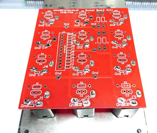
Specific Information on the 12 Way 1/4" Mono Jack Socket PCB (28x 22y Pitch). Board size: 87x75mm
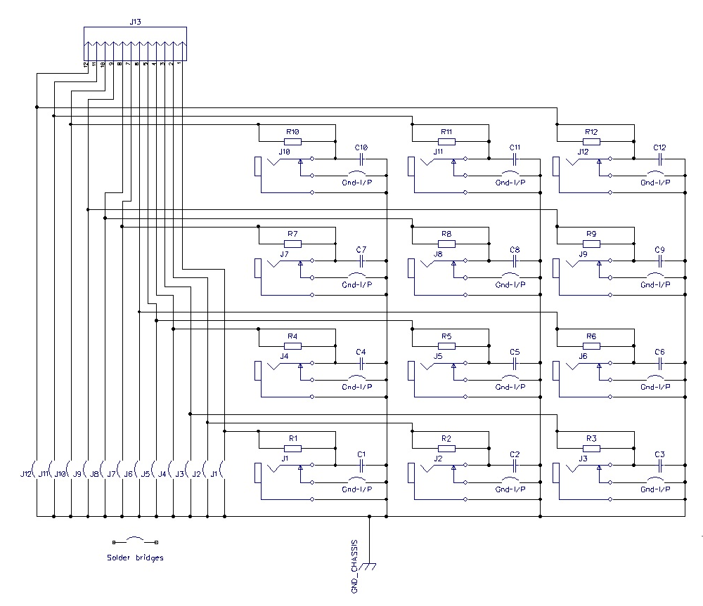
7210-734 accommodates 12 of our Switchcraft jack sockets on a 28mm horizontal pitch and 22mm vertical pitch. Click the schematic image above to see the circuit for this board. All sockets have their ground connections commoned together, each of the socket signal connections are wired to 12 way JST connector. You can solder in the required number of sockets to match the particular project front panel. Additionally, the board has a number of options such as including a resistor in the socket signal line, a capacitor across any of the jack sockets, 4 resistors in a kludge area and finally any of the JST connections can be grounded using solder links. Where any of these options are required, it is specifically mentioned in the ST Synth Panel Breakout PCB Set for the MFOS project.
Solderable Links:
12 solderable jumpers labelled J1 to J12 used to ground any of the JST wire connections from unused sockets. This allows you to connect the board ground to the MFOS main board or to further distribute ground wiring around the panel.
Each socket has a 'Gnd I/P' link, when soldered across, it grounds the socket input terminal when no jack plug is inserted. Whilst we are not aware of any MFOS project that requires this, it has been included for future use once we have evaluated the benefits or otherwise in certain projects.
There are also 4 Ground (0V) pads just in case.
Note: Sockets are numbered 1-12 when viewed from the rear and count from bottom left to top right.
Assembly
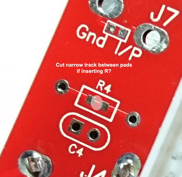
- First cut any tracks for resistors if required
- Solder across any jumpers as required
- Solder in any resistors or capacitors if required
- Solder in the JST socket noting that the slots in the socket housing point towards the left of the board (towards J4 & J7)
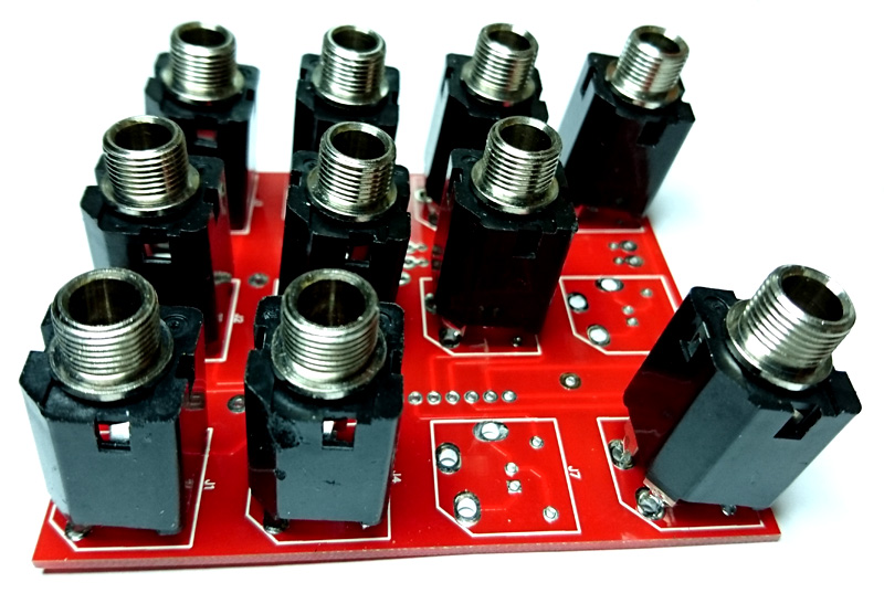
- Place the jack sockets into the underside of the PCB to match the front panel hole layout
- Place the back panel over the sockets and fit a couple of lock nuts
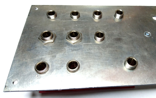
- Carefully turnover the panel whilst retaining the sockets and PCB and place on a couple of books, strips or whatever you have to hand to ensure the socket threads are not resting on the bench.
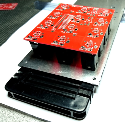
- After ensureing all sockets are sat properly on the panel, you can commence soldering the socket terminals. Whilst the photo does not show the JST socket in position, it is far easier to solder it as described in step 4 above first.
- Once soldering is complete, you can remove the socket lock nuts fitted in step 6 and remove the PCB until you are ready for final assembly.
Wiring Colour Code
Pin 1 (black wire) is on the bottom next to J1 solder bridge
| Colour | Function |
| Black | Skt 1 Sig |
| Red | Skt 2 Sig |
| White | Skt 3 Sig |
| Yellow | Skt 4 Sig |
| Orange | Skt 5 Sig |
| Green | Skt 6 Sig |
| Blue | Skt 7 Sig |
| Violet | Skt 8 Sig |
| Grey | Skt 9 Sig |
| Brown | Skt 10 Sig |
| Black | Skt 11 Sig |
| Red | Skt 12 Sig |
It is always worth checking the wire colour sequence to ensure it matches the above just in case there has been a mistake at the factory in the assembly of the cable.
Typical examples of projects that use this board: VCO.