

A bare through hole plated PCB for the Soundtronics Attack, Decay, Sustain, Release 3310 Envelope Generator.
- 1mS to 30 second Attack, Decay, and Release times.
- Re-trigger input permits retrigger of the attack phase during the decay period
- Supply voltage +/- 12V as standard, change 6 resistors for +/- 15V operation
- Range switch offers finer adjustment for short timing periods
- Comparator on gate input making it suitable for gate pulses >2.5V
- Manual gate switch
- Twin ADSR outputs
- PCB suitable for 4 types of power supply connector - Soundtronics, Eurorack, Dotcom and MOTM
- Full 10V swing on ADSR output
- Optional JST leads for all connections although you can hardwire if you prefer
- Optional jack socket PCB 7210-722 simplifies wiring
For circuit schematic and PCB layout, see the 'Downloads' tab.
As builders have differing preferences and build formats, the parts list below excludes knobs, JST sockets, 1/4" jack sockets and panels all of which are available from Soundtronics. See the ADSR 3310 main page here for further related products.
| Qty Reqd. | Description | Value | Designators | ST part No. |
| 1 | 33nF 2.5mm X7R Dielectric Radial Ceramic Capacitor | 33nF | C11 | 2069-070 |
| 3 | 200R 0.25W 1% Metal Film Resistor | 200R | R16, R17, R19 (15V) | 7163-034 |
| 3 | 270R 0.25W 1% Metal Film Resistor | 270R | R16, R17, R19 (12V) | 7163-037 |
| 1 | 470R 0.25W 1% Metal Film Resistor | 470R | R22 (12V) | 7163-043 |
| 1 | 750R 0.25W 1% Metal Film Resistor | 510R | R22 (15V) | 7163-048 |
| 2 | 1k 0.25W 1% Metal Film Resistor | 1k | R13, R23 | 7163-051 |
| 5 | 10k 0.25W 1% Metal Film Resistor | 10k | R1, R5, (R20 15V), R21, R24 | 7163-075 |
| 3 | 12k 0.25W 1% Metal Film Resistor | 12k | R9, R12, R15 (15V) | 7163-077 |
| 3 | 13k 0.25W 1% Metal Film Resistor | 13k | R9, R12, R15 (12V) | 7163-078 |
| 1 | 15k 0.25W 1% Metal Film Resistor | 15k | R20 (12V) | 7163-079 |
| 4 | 20k 0.25W 1% Metal Film Resistor | 20k | R2, R4, R6, R14 | 7163-082 |
| 1 | 30k 0.25W 1% Metal Film Resistor | 30k | R11 | 7163-086 |
| 4 | 100k 0.25W 1% Metal Film Resistor | 100k | R3, R8, R10, R18 | 7163-099 |
| 1 | 1M 0.25W 1% Metal Film Resistor | 1M | R7 | 7163-122 |
| 1 | SPDT Miniature Toggle Switch | SPDT | 7212-250 | |
| 1 | Low Profile Push to Make Switch, Red | Red | 7212-253 | |
| 1 | Turned Pin 0.3 inch Dil IC Socket 14 Pin | U1 | 7212-332 | |
| 1 | Turned Pin 0.3 inch Dil IC Socket 16 Pin | U2 | 7212-333 | |
| 4 | 1N914 75V Signal Diode | D1, D2, D3, D4 |
7212-486 | |
| 1 | 3n3 5mm X7R Dielectric Radial Ceramic Capacitor | 3n3 | C8 | 7212-743 |
| 1 | 4n7 5mm X7R Dielectric Radial Ceramic Capacitor | 4n7 | C12 | 7212-744 |
| 2 | 10nF 5mm X7R Dielectric Radial Ceramic Capacitor | 10nF | C9, C10 | 7212-746 |
| 5 | 100nF 5mm X7R Dielectric Radial Ceramic Capacitor | 100nF | C1, C2, C4, C5, C7 | 7212-749 |
| 2 | Radial Electrolytic Capacitor 100uF 25V | 100uF 25V | C3, C6 | 7213-110 |
| 1 | Quad Op-Amp BiFET TL084 | U1 | 7212-564 | |
| 1 | AS3310 ADSR Envelope Generator 16-Pin DIP | U2 | 7212-588 | |
| 4 | Synth Pot 16mm 100k Lin | VR1 , VR2, VR3, VR4 | 7300-255 |
* Note parts list includes resistors for both +/-12V and +/-15V versions
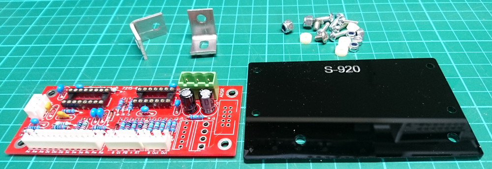
This guide is for the construction of the Soundtronics ADSR 3310 in 5U format. Please read through all of the instructions first before commencing as there are some pointers that could make assembly easier.
All parts needed are available from soundtronics.co.uk including:
- PCB: 7215-020
- Electronic components kit: 7215-220
- Front panel: 7215-520
- Back panel: 7215-820
- PCB holder: 7215-920
- PCB fixings: 7210-182
- Angle brackets: 7210-181
- Switchcraft jack sockets: 7212-204
- Cliff KM20B knobs: 7210-104
- Jack sockets breakout PCB: 7210-722
- Your choice of power connector
- Soundtronics 1251-054
- MOTM 7212-305
- Dotcom 7212-302
- Eurorack 7212-301
- JST leads
- 3-way: 7210-103
- 5-way: 7210-105
- 12-way: 7210-112
Not all of the above are absolutely necessary. For example you can hard wire the PCB connections to pots, switches and sockets.
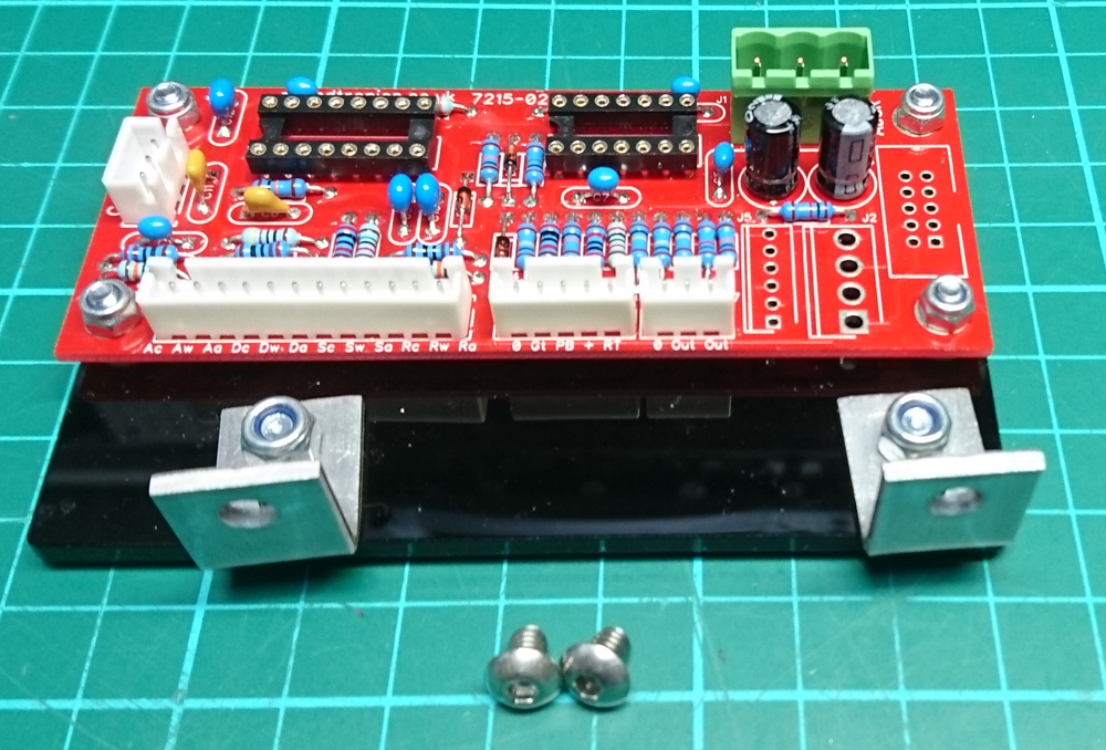
Step 1:
Mount you assembled PCB (7215-020) to the PCB holder (7215-920) using the fixings set (7210-181 and 7210-181).
Keep the angle bracket loose at this stage but the 4 PCB fixings can be tightened up, no need to over-tighten otherwise you risk shattering the PCB holder. When assembled you have ...
Step 2:
Bring the front and back panels together and fit the pots, switches and sockets.
Tips
- Do not use pliers to tighten up the pot, switch and socket nuts as you risk scratching the panel and damaging the zinc plating on the nuts. Use sockets or nut spinners:
- Pots use 10mm
- Toggle switch use 8mm
- Jack sockets use 13mm
- Do not over-tighten the nuts, especially on the pots as it is quite easy to strip their threads
- We do not use washers behind the pot and toggle switch nuts
- If you do not want a range switch, link out J8 as shown on the PCB. You can also then exclude C12.
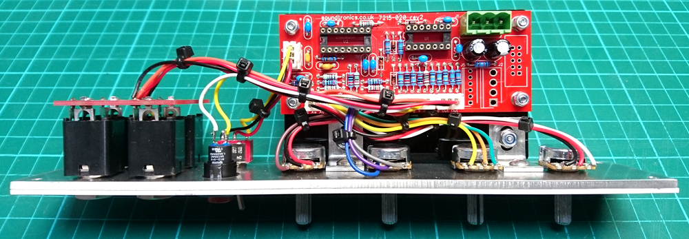
When viewed from the rear, orientate the jack sockets so that the flat corner is to the bottom left, the pot solder tags point to the right, the toggle switch is mounted vertically. You can also fix the PCB holder angle brackets to the back panel using M4x5 screws that came with the brackets. The photo below of the completed assembly makes the above clearer.
Step 3:
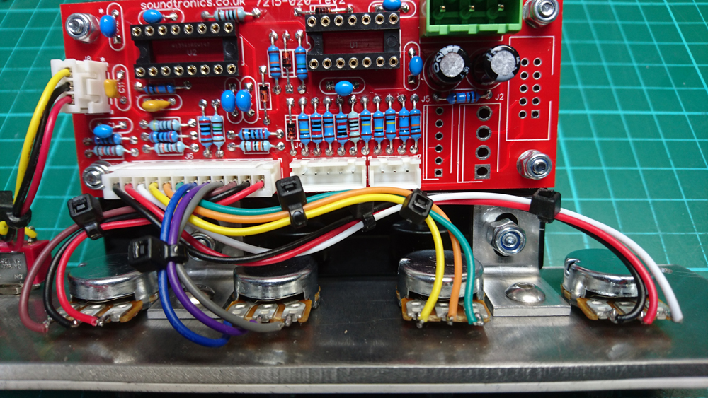
Wiring to the pots using a 12-way JST connector (7210-112) is colour coded where Pin 1 is nearest the corner of the PCB:
| 1 | Ac | Black | Attack pot CW |
| 2 | Aw | Red | Attack pot wiper |
| 3 | Aa | White | Attack pot CCW |
| 4 | Dc | Yellow | Decay pot CW |
| 5 | Dw | Orange | Decay pot wiper |
| 6 | Da | Green | Decay pot CCW |
| 7 | Sc | Blue | Sustain pot CW |
| 8 | Sw | Violet | Sustain pot wiper |
| 9 | Sa | Grey | Sustain pot CCW |
| 10 | Rc | Brown | Release pot CW |
| 11 | Rs | Black | Release pot wiper |
| 12 | Ra | Red | Release pot CCW |
Where CW = clockwise, CCW = counter-clockwise
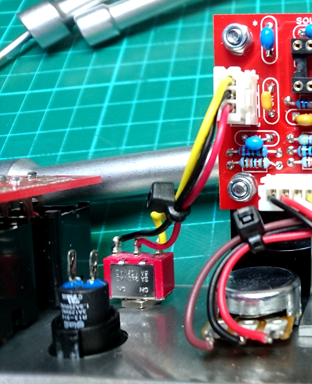
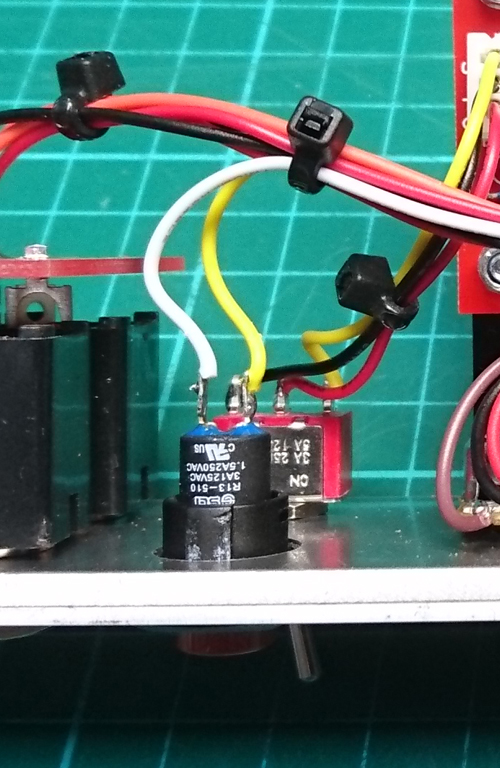
This close up photo helps:
Step 4:
You may find it easier to take a 3-way JST lead (7210-103), cut leads to 50mm length and solder to the switch prior to mounting the switch to the panel. The red wire must connect to the centre tag on the switch. There are two 3-way JST sockets on the PCB, for the table below it is the socket marked as 'CLS'.
| 1 | S | Yellow | Range switch top connection |
| 2 | L | Black | Range switch bottom connection |
| 3 | C | Red | Range switch centre connection |
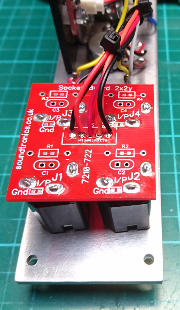
Step 5:
Wiring to the jack socket board and push button. First solder the jack socket breakout PCB (7210-722) to the tags on the jack sockets after first making sure the sockets are orientated with the flat corner to the bottom left when viewed from the rear.
Plug in the 5-way JST lead (7210-105) and the 3-way JST lead (7210-103) into the PCB sockets, the 3-way plugs into the socket marked '0 Out Out'. The yellow wire on the 3-way JST lead can be cut off as not need when using the breakout PCB.
| 1 | 0 | Yellow | Cut |
| 2 | Out | Black | Jack socket PCB - 1 |
| 3 | Out | Red | Jack socket PCB - 3 |
| 1 | 0 | Black | Jack socket PCB - 5 |
| 2 | Gt | Red | Jack socket PCB - 2 |
| 3 | PB | White | Push button |
| 4 | + | Yellow | Push button |
| 5 | RT | Orange | Jack socket PCB - 4 |
Assembly has now been completed and you can proceed to testing. Before inserting the chips, power up the board first and double check supply polarity on the socket for U1 (TL084). With respect to ground 0V, pin 4 is +12V and pin 7 is -12V or +/-15V if that is your power supply voltage.
After removing power, proceed with plugging in the chips ensuring correct orientation. As there is no setting up, you are ready to go and test its operation.
How it works:
Much of the hard work is carried out by the AS3310 ADSR chip. The attack, decay and release periods are set by applying a voltage of between 0 and -240mV to the respective pins which is derived from the ADR pots. Each ADR pot is applied to a potential divider which reduces the pot voltage of -12V (or -15V) to just over -240mV.
For -12V operation, each potential divider of R9/R19, R12/R16 & R15/R17 uses 3k/270R resistors so -12V gives -244mV. For -15V operation with 12k/200R gives 246mV.
The sustain input to the AS3310 is similar but requires a 0 to +5V signal to give a 0-100% of the peak attack voltage. Once again this is achieved using a potential divider from the sustain pot R14/R20. For 12V this is 20k/15K = 5.14V, for 15V this is 20k/10k giving 5V.
The AS3310 requires a bipolar supply but the negative supply to Vee is limited to 7V whereas the positive supply Vcc can go to 18V. R22 is used to set the Vee supply which is calculated using the formula:
R22=(supply voltage -7.5)/0.01
For 12V, this gives 450R, nearest preferred value being 470R. For 15V, it is 750R.
The AS3310 requires both a gate pulse and a trigger pulse simultaneously to start the ADSR cycle. Fortunately, we can create the trigger pulse from the gate pulse using a capacitor - C8. The gate pulse can come from either the manual pushbutton or the gate socket. The pushbutton has a CR contact debounce before joining with the gate socket input at U1.1 non-inverting input. U1.1 is a comparator that quickly flips its output from negative to positive saturation when the non-inverting input (pin 3) voltage exceeds 2V (for 12V operation or 2.5V for 15V operation). The threshold is set by R3 & R2 at the inverting input (pin 2). The comparator output is fed to the AS3310 gate input via D3 to ensure the AS3310 only sees positive voltages. During the delay phase, and pulses coming in from the re-trig socket will re-trigger the attack phase via D4 and C10.
The ADSR envelope output from the AS3310 is buffered by U1.3 and U1.2 before feeding the output sockets via R13 and R23.
There is a risk that the sustain voltage could exceed the peak attack voltage giving undesirable results. Pin 3 of the AS3310 outputs the peak attack voltage which is connected to a precision peak follower U1.4 which is connected to the sustain voltage input of AS3310 pin 9 to prevent this situation.