

Synth Modular Cabinet Construction
We are certainly no master carpenters but knew that our in-house development synth deserved something befitting for the cabinet. The cabinet is designed to house 4 rows, 22U wide of modules making 88U in total.
Sides
We chose to use American white oak timber throughout which apart from looking good was available locally at our timber merchants. The 4 sides where assembled from 225x25mm planks. Each plank was cut to length on a table saw and then the edges were finished on our metal working milling machine! This actually give a really clean and square finish to the ends but what we really needed was a thickener planner as the thickness of the planks were variable and slightly warped. Despite the lack of thickener, we were confident that we could still get good results.
The corners were fixed using camlock fixings, glue and wooden dowels but the camlock fixings were basically rubbish. They were made from aluminium and so soft, even with a moderate tightening, they deformed. Too late to turn back now so we persevered and eventually got the sides assembled. To ensure squareness, use a tape measure across opposite corners and distort the frame until both dimensions are equal.
Module Frame
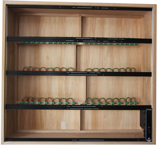
We could have made up a timber frame to screw the modules to but decided on making up a frame based around OpenBeam which we stock on our Makertronics site. These 15mm square profile aluminium extrusions are cut down from their original 1m lengths to 22U long (978mm). The OpenBeam take M3 nuts which you slide into the channel to which you can then use M3 machine screws to attach the modules. We actually slide in enough nuts to fix plenty of modules to as they cannot be inserted after assembly into the cabinet. A note for next time is to open up the channel with a milling cutter or drill bit at a couple of locations on each rail to allow nuts to be added post installation.
Each rail comes with a plain hole all the way through making it very easy to then tap this hole at each end with a M3 tap. We then took some flat aluminium strip and drill out holes at 209.25mm centres for our modules allowing for a 2mm gap between panel rows. Our module panels already have their fixing holes positioned such that when used with OpenBeam, there is a 1mm gap top and bottom. The assembled frame is then fixed into the cabinet using self tappers making sure pilot holes are drilled into the cabinet first as American oak is rather hard!
Rear Frame
The rear frame is again constructed from American white oak of nominal size 19x38mm. Each vertical baton is rebated into the horizontal batons. We cut the rebates using the trusty milling machine although next time we will use a thicker baton so we can keep all of the vertical batons in line. This rear frame is to both accommodate the rear panels and the power distribution. The rear panels were cut from 5.5mm thick plywood with a white oak veneer. Cutting was actually very easy for us as we used our laser cutter which also cut the mounting holes as well.
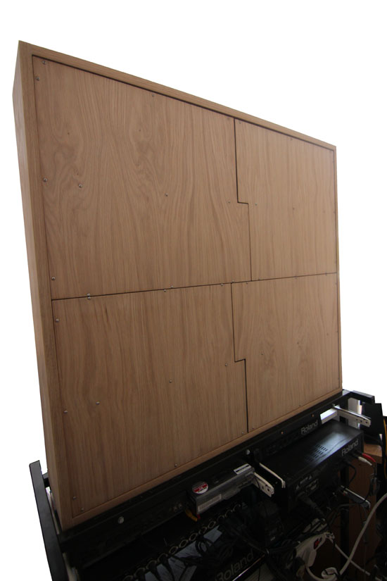
Not a good angle to take a picture from but you get the idea.
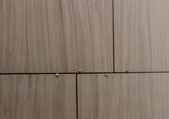
The fixing screws are M3 stainless steel button heads 22mm long. As the batons are white oak and thus a hard wood, the fixing holes were tapped out M3.
We still need to cut out the rear panel to take the power inlet panel and maybe laser engrave our logo but other than that, it is complete.
Power Distribution
There are many ways of distributing power to the modules. We thought we would try out this method using our chassis mount terminal blocks. These have been daisy chained into 6 banks of 9 (top row 2x11) connectors that should be sufficient to plug in all of the modules we plan on installing. One connector from each row is used to plug in power for that bank and is wired back to the main +/-12Vdc power supply (pic to follow on next update).
The method of wiring was to use 1.5mm2 cabling with each joint terminated using twin entry bootlace ferrules (start and finish connections using standard single entry bootlace ferrules)
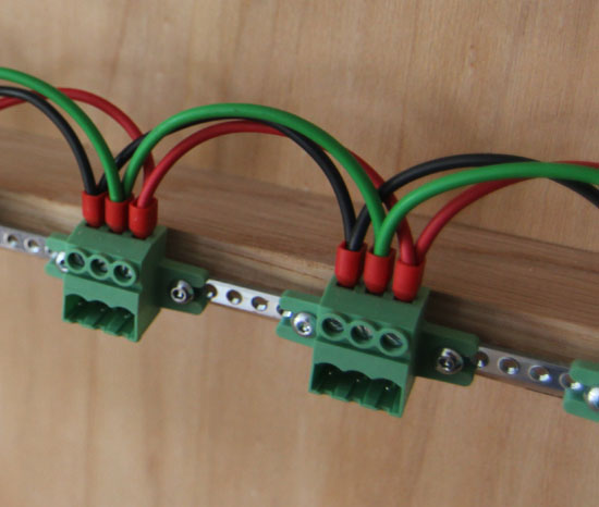
The connector blocks were fixed to a tapped steel strip with holes at a 0.2" pitch. The pitch is not quite right if you are butting together the blocks but you can get away with it for the 5 blocks or so before you need to leave a gap. We do not list the tapped strip, cabling or bootlace ferrules at the time of writing this but we do have them here so if you need some just let us know.
In the next update we will complete the power distribution in readiness to start populating with modules.
There are no products in this section