

Chord VCO 102 Build Guide
Assembly Instructions
The Chord VCO 102 module has particular build requirements but we do recommend also reading the ‘General Build Info' page.
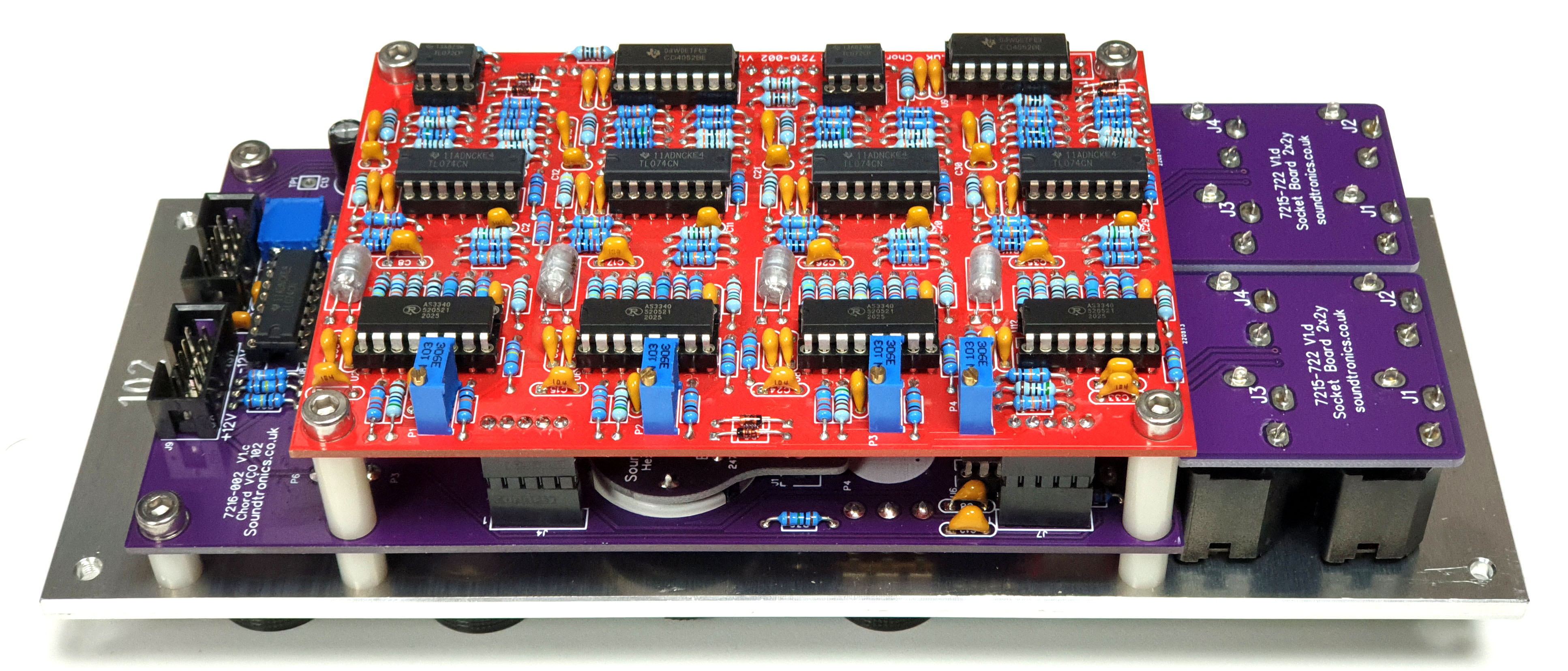
The Chord VCO module differs from most other modules in that it has two PCBs double stacked. Assembly of each individual PCB is straightforward and covered in the General Guidance’ booklet. Minor differences are:
- Four x 5-way + 1 x 2-way female headers are soldered to the components side of the pot PCB and to the underside of the VCO PCB.
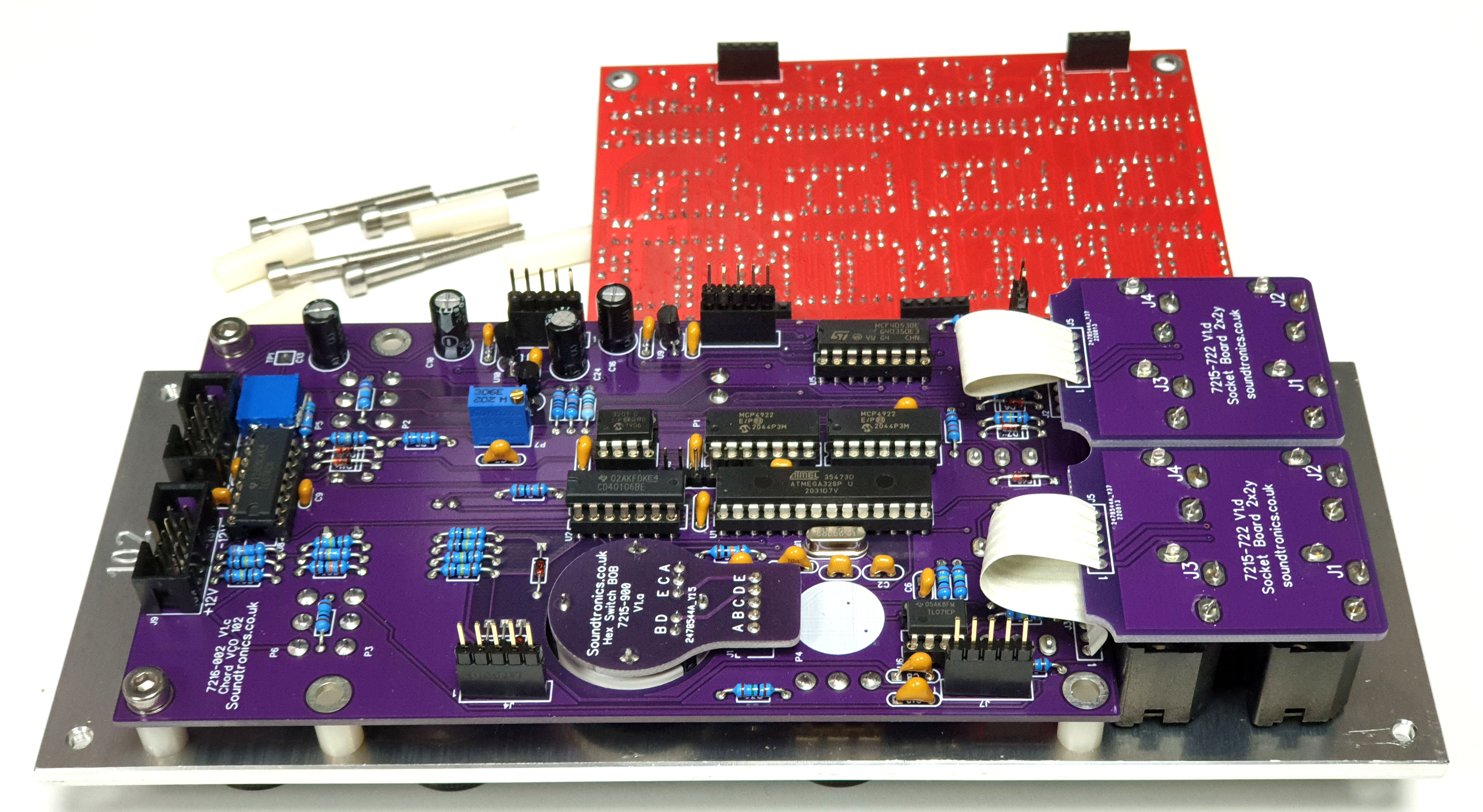
3. Soldering the headers and keeping them upright can be tricky. We find ‘dry’ assembling the two PCBs together and to the back panel first. Then solder the headers on the VCO PCB, remove from the back plate and solder the headers on the Pot PCB.
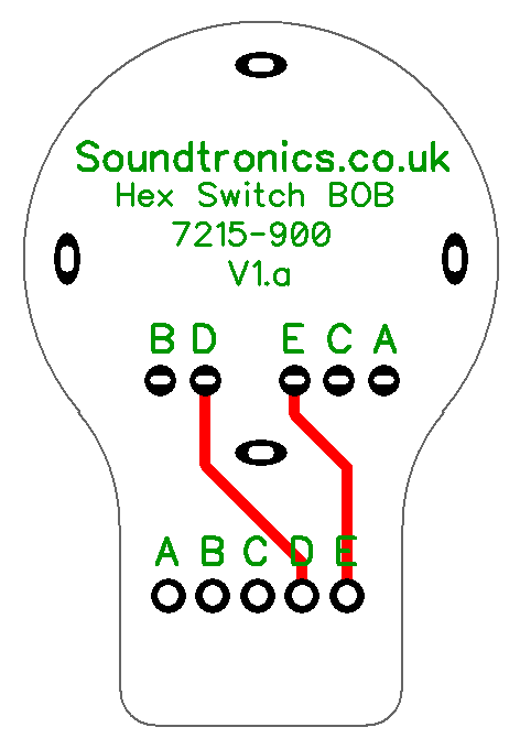
4. The chord switch header should be soldered to the Pot PCB first, fix the Pot PCB to the back panel and mount the 16-way chord switch. Place the breakout PCB 7215-900 over the switch and header pins and solder in place.
Calibration
- Before fitting the piggyback VCO PCB, power up module and allow to ‘warm up’ for 5 minutes
- Using Pr2, adjust the voltage at TP1 to 4.266V
- Power down and fit the VCO piggyback PCB
 4. Set the coarse and fine controls to 0%, quantize off, VCO’s x3/4, pulse waveform and PWM initial width to 50%.
5. Apply a 5V CV to the V/Oct input
6. Using Pr1, adjust the voltage at pin 3 (middle pin near R121) of J6 to 2.8V
7. Apply a CV of 6V, set chord to CM7 then using P1, adjust the VCO 1 output frequency to 2093Hz. Repeat for P2/VCO 2 but 2637Hz, P3/VCO3 but 3136Hz and finally P4/VCO4 for 3951Hz.
8. Carry out an auto tune.
Oscillator PCB Parts List
Part Number |
Quantity |
Value |
Name |
RefDes |
| 7212-746 | 12 | 10n | 10n MLCC 5.08mm Capacitor | C1, C5, C8, C10, C14, C17, C19, C23, C26, C28, C32, C35 |
| 7212-731 | 12 | 22p | 22p MLCC Capacitor | C2, C3, C9, C11, C12, C18, C20, C21, C27, C29, C30, C36 |
| 2069-220 | 4 | 1n Polystyr | Radial Polystyrene | C4, C13, C22, C31 |
| 7212-749 | 28 | 100n | 100n MLCC 5.08mm Capacitor | C6, C7, C15, C16, C24, C25, C33, C34, C37, C38, C39, C40, C41, C42, C43, C44, C45, C46, C47, C48, C49, C50, C51, C52, C53, C54, C55, C56 |
| 7212-486 | 8 | 1N914 | 1N914 | D1, D2, D3, D4, D5, D6, D7, D8 |
| 1208-035 | 4 | 5-Way Female Header | J1, J2, J3, J4 | |
| 1208-032 | 1 | 2-Way Female Header Type A | J5 | |
| 7212-857 | 4 | 10k | 10k Preset 25T 3296W | P1, P2, P3, P4 |
| 7163-075 | 20 | 10k | 10k 0.25W 1% Metal Film Resistor | R1, R10, R12, R16, R21, R36, R46, R48, R52, R56, R71, R80, R82, R85, R90, R106, R117, R119, R123, R127 |
| 7163-099 | 9 | 100k | 100k 0.25W 1% Metal Film Resistor | R2, R18, R37, R38, R72, R98, R107, R108, R109 |
| 7163-051 | 16 | 1k | 1k 0.25W 1% Metal Film Resistor | R3, R15, R25, R34, R39, R51, R60, R69, R73, R84, R94, R104, R110, R122, R131, R140 |
| 7163-082 | 4 | 20k | 20k 0.25W 1% Metal Film Resistor | R4, R40, R74, R111 |
| 7163-112 | 4 | 360k | 360k 0.25W 1% Metal Film Resistor | R5, R41, R75, R112 |
| 7163-043 | 8 | 470R | 470R 0.25W 1% Metal Film Resistor | R6, R26, R42, R61, R76, R95, R113, R132 |
| 7163-101 | 16 | 120k | 120k 0.25W 1% Metal Film Resistor | R7, R17, R24, R27, R43, R53, R59, R62, R77, R86, R93, R96, R114, R124, R130, R133 |
| 7163-122 | 4 | 1M | 1M 0.25W 1% Metal Film Resistor | R8, R44, R78, R115 |
| 7163-103 | 16 | 150k | 150k 0.25W 1% Metal Film Resistor | R9, R13, R19, R28, R45, R50, R54, R63, R79, R87, R88, R97, R116, R121, R125, R134 |
| 7163-070 | 4 | 6k2 | 6k2 0.25W 1% Metal Film Resistor | R11, R47, R81, R118 |
| 7163-128 | 4 | 1M2 | 1M2 0.25W 1% Metal Film Resistor | R14, R49, R83, R120 |
| 7163-081 | 4 | 18k | 18k 0.25W 1% Metal Film Resistor | R20, R55, R89, R126 |
| 7163-057 | 4 | 1k8 | 1k8 0.25W 1% Metal Film Resistor | R22, R57, R91, R128 |
| 7163-055 | 4 | 1k5 | 1k5 0.25W 1% Metal Film Resistor | R23, R58, R92, R129 |
| 7163-069 | 4 | 5k6 | 5k6 0.25W 1% Metal Film Resistor | R29, R64, R99, R135 |
| 7163-110 | 8 | 300k | 300k 0.25W 1% Metal Film Resistor | R30, R35, R65, R70, R100, R105, R136, R141 |
| 7163-058 | 4 | 2k | 2k 0.25W 1% Metal Film Resistor | R31, R66, R101, R137 |
| 7163-083 | 8 | 22k | 22k 0.25W 1% Metal Film Resistor | R32, R33, R67, R68, R102, R103, R138, R139 |
| 7212-544 | 4 | TL074 | U1, U4, U7, U10 | |
| 7212-591 | 4 | AS3340 | U2, U6, U8, U12 | |
| 7212-525 | 2 | 4052B | U3, U9 | |
| 7212-542 | 2 | TL072 | U5, U11 |
Pot PCB Parts List
| Part Number | Quantity | Value | Name | RefDes |
| 7212-751 | 1 | 1u | 1u MLCC 5.08mm Capacitor | C1 |
| 7212-731 | 3 | 22p | 22p MLCC Capacitor | C2, C3, C6 |
| 7212-749 | 11 | 100n | 100n MLCC 5.08mm Capacitor | C4, C7, C8, C12, C14, C17, C18, C19, C20, C21, C23 |
| 7212-745 | 1 | 10n | 10n MLCC Capacitor | C5 |
| 7212-768 | 2 | 100n | 100n MLCC Capacitor | C9, C11 |
| 7213-110 | 4 | 100u | 100uF 25V Electrolytic | C10, C13, C16, C24 |
| 7212-750 | 2 | 220n | 220n MLCC Capacitor | C15, C22 |
| 1208-046 | 1 | FTDI | FTDI Interface | Conn1 |
| 7213-921 | 1 | LED - Yellow | D1 | |
| 7212-486 | 10 | 1N914 | D2, D3, D4, D5, D6, D7, D8, D9, D10, D11 | |
| 7212-486 | 1 | 1N914 | 1N914 | D12 |
| 7212-262 | 1 | Hex Switch | JST_XH_5way | J1 |
| 1208-005 | 2 | Flex Strip 5way | J2, J3 | |
| 1208-035 | 4 | 5-Way Female Header | J4, J5, J6, J7 | |
| 1208-032 | 1 | 2-Way Female Header Type A | J8 | |
| 7212-301 | 2 | Eurorack | Eurorack Power | J9, J10 |
| 7300-820 | 6 | 100k Lin | Pot 100k Lin PCB Angle | P1, P2, P3, P4, P5, P6 |
| 7212-859 | 1 | 50k | 50k Preset 25T 3296W | Pr1 |
| 7212-855 | 1 | 2k | 2k Preset 25T 3296W | Pr2 |
| 7163-051 | 6 | 1k | 1k 0.25W 1% Metal Film Resistor | R1, R27, R28, R29, R30, R31 |
| 7163-075 | 3 | 10k | 10k 0.25W 1% Metal Film Resistor | R2, R25, R34 |
| 7163-099 | 12 | 100k | 100k 0.25W 1% Metal Film Resistor | R3, R4, R5, R6, R10, R11, R16, R18, R22, R23, R24, R26 |
| 7163-101 | 2 | 120k | 120k 0.25W 1% Metal Film Resistor | R7, R17 |
| 7163-089 | 1 | 39k | 39k 0.25W 1% Metal Film Resistor | R8 |
| 7163-055 | 1 | 1k5 | 1k5 0.25W 1% Metal Film Resistor | R9 |
| 7163-106 | 4 | 200k | 200k 0.25W 1% Metal Film Resistor | R12, R13, R14, R15 |
| 7163-092 | 1 | 51k | 51k 0.25W 1% Metal Film Resistor | R19 |
| 7163-086 | 1 | 30k | 30k 0.25W 1% Metal Film Resistor | R20 |
| 7163-122 | 2 | 1M | 1M 0.25W 1% Metal Film Resistor | R21, R32 |
| 7163-039 | 1 | 330R | 330R 0.25W 1% Metal Film Resistor | R33 |
| 7163-078 | 1 | 13k | 13k 0.25W 1% Metal Film Resistor | R35 |
| 7212-250 | 3 | SPDT | S1, S3, S5 | |
| 7212-264 | 1 | Tactile Synth PB | S2 | |
| 7212-251 | 1 | SPDT CO | S4 | |
| 7212-604 | 1 | ATMEGA328P-PU | ATMEGA328P-PU | U1 |
| 7212-521 | 1 | 40106B | U2 | |
| 2254-012 | 2 | MCP4922 | U3, U4 | |
| 7212-526 | 1 | 4053B | U5 | |
| 7212-541 | 1 | TL071 | U6 | |
| 2254-013 | 1 | MCP3201 | U7 | |
| 7212-544 | 1 | TL074 | U8 | |
| 2230-021 | 1 | -5V | 79L05 | U9 |
| 2230-011 | 1 | 5V | 78L05 | U10 |
| 2230-302 | 1 | TL431CLP | U11 | |
| 2121-161 | 1 | 16MHz | 16MHz Crystal | Xtal1 |
Module Parts List
| Description | Reference | MOTM Qty | MU Qty | Notes |
| Pot Sticky Pads | 7210-188 | 6 | 6 | |
| 10mm M4 Spacers | 7210-186 | 6 | 6 | |
| 20mm M4 Spacers | 7210-190 | 4 | 4 | |
| M4 x 14 Cap Head Screws | 7210-187 | 2 | 2 | |
| M4 x 35 Cap Head Screws | 7210-194 | 4 | 4 | |
| Toggle Switch Dress Nut | 7210-196 | 4 | 4 | |
| M3 x 8mm Stainless Panel Screws | 7216-151 | 4 | ||
| 8-Pin IC Socket | 7212-331 | 4 | 4 | |
| 14-Pin IC Socket | 7212-332 | 8 | 8 | |
| 16-Pin IC Socket | 7212-333 | 7 | 7 | |
| 28-pin IC Socket | 7212-338 | 1 | 1 | |
| Power Lead | 7216-164 | 2 | ||
| Extended Male Header 22-way | 1208-055 | 1 | 1 | Cut to size |
| 5-way Header | 1208-045 | 1 | 1 | For 7215-900 PCB |
| LED Spacer | 7210-185 | 1 | 1 | |
| Hex switch | 7212-262 | 1 | 1 | |
| Hex Switch Knob MOTM | 1 | |||
| Hex Switch Knob MU | 1 | |||
| Hex Switch Brass Spacer | 1 | |||
| MU Voltage module | 2 | |||
| MOTM Front Panel | 7216-502 | 1 | ||
| MOTM Back Panel | 7216-802 | 1 | ||
| MU Front and Back Panel | 7219-502 | 1 | ||
| Pot PCB | 7216-002-Pot | 1 | 1 | |
| VCO PCB | 7216-002-VCO | 1 | 1 | |
| Jack Socket PCB | 7215-722 | 2 | 2 | |
| 16-Way Switch Breakout PCB | 7215-900 | 1 | 1 | Chord selection |
| Jack Sockets | 7212-220 | 8 | 8 | |
| B100k Pots Long Shaft | 7300-820 | 6 | ||
| B100k Pots Short Shaft | 7300-821 | 6 | ||
| KM20B Knobs | 7212-170 | 6 | ||
| MU Knobs | 7212-169 | 6 | ||
| VCO Circuit Schematic | S-7216-002-c | 1 | 1 | 3 sheets |
| Pot Circuit Schematic | S-7216-002-d | 1 | 1 | 3 sheets |
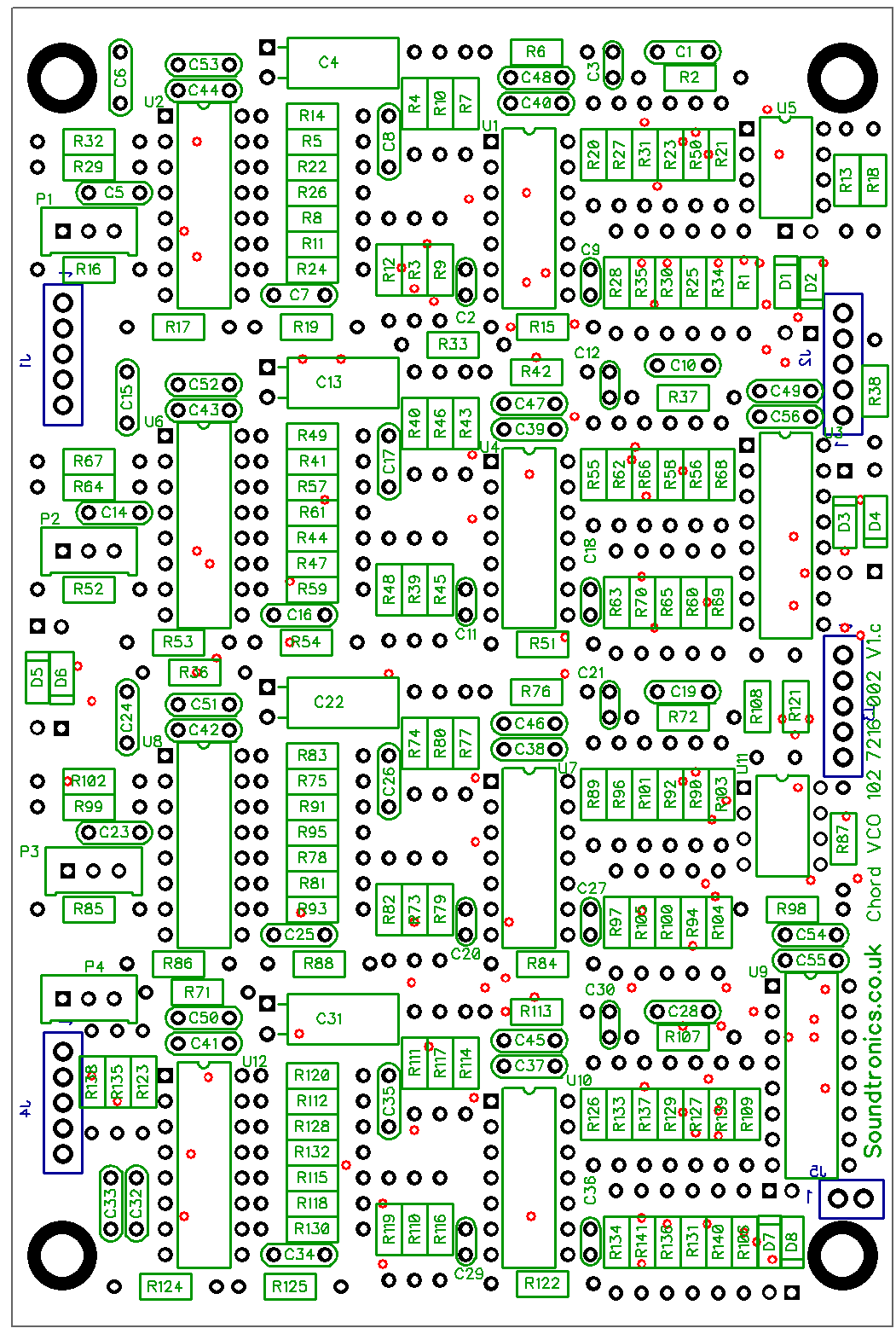
Oscillator PCB Layout
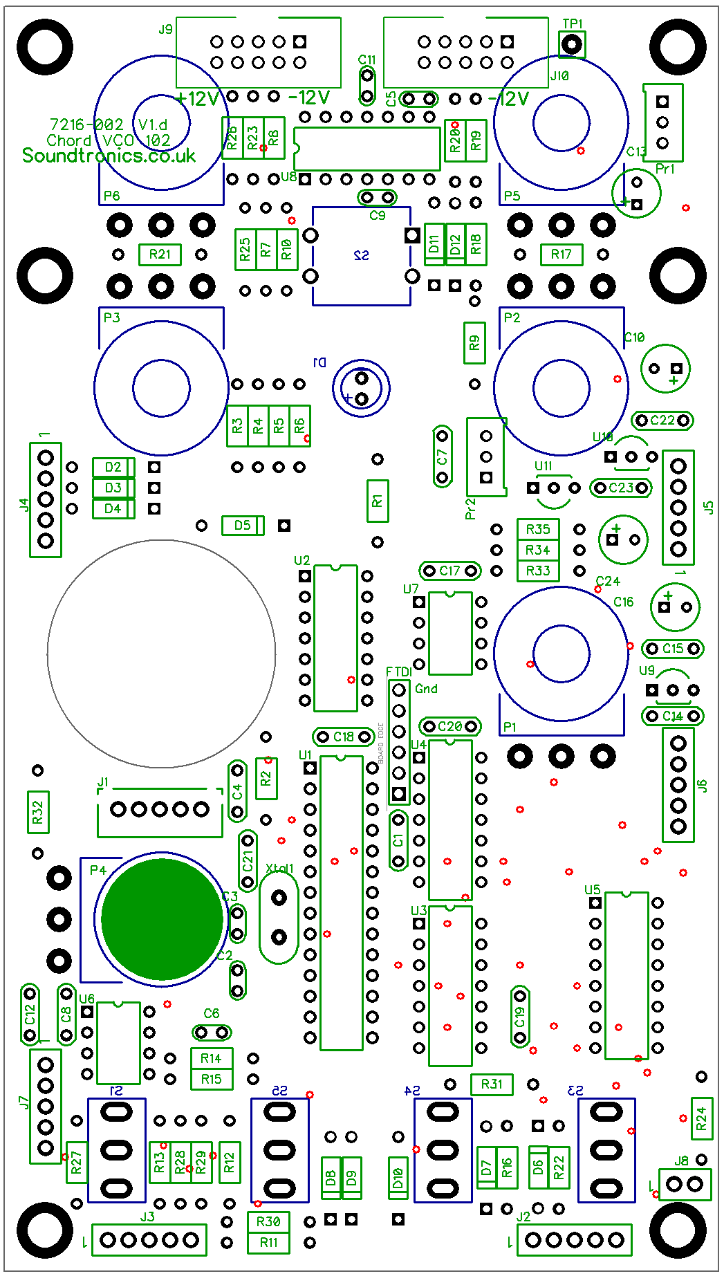
Pot PCB Layout
Rotary Switch BOB
There are no products in this section