

SV VCF 112 Build Guide
Assembly Instructions
The SV VCF 112 module has no particular build requirements not already covered in the ‘General Build Info' page.
Calibration
- Power up module and allow to ‘warm up’ for 10 minutes
- Connect a CV source to the Common CV input, a scope and frequency meter to the Mix Out
- Set all toggle switches to the down ‘Signal In’ position, all pots fully CCW
- The V/octave is set for each individual filter. If the frequency is flat (<target), use the specified trimmer and make the frequency lower (flatter), if above target frequency, use the trimmer to make the frequency even higher, this can be counter-intuitive. You will soon get the feel of how much to increase or decrease the frequency by
- LP Filter – LP Mix pot fully CW, Resonance pot fully CW, CV to 0V
- Adjust LP Cut-Off to giver an output self-oscillating frequency of 50Hz
- Set CV to 5V, output frequency should be 1.6kHz, if not adjust PR1 as described in step 4
- Repeats steps 5-7 until 1.6kHz, then set LP Mix pot fully CCW
- HP Filter – HP Mix pot fully CW, Resonance fully CW, CV to 0V
- Adjust HP Cut-Off to giver an output self-oscillating frequency of 50Hz
- Set CV to 5V, output frequency should be 1.6kHz, if not adjust PR2 as described in step 4
- Repeats steps 9-11 until 1.6kHz, then set HP Mix pot fully CCW
- BP Filter – BP Mix pot fully CW, Resonance fully CW, CV to 0V
- Adjust HP Cut-Off to giver an output self-oscillating frequency of 20Hz
- Set CV to 5V, output frequency should be 640Hz, if not adjust PR3 as described in step 4
- Repeats steps 13-15 until 640Hz, then set BP Mix pot fully CCW
- BP Filter – BP Mix pot fully CW, Resonance fully CW, CV to 0V
- Adjust HP Cut-Off to giver an output self-oscillating frequency of 20Hz
- Set CV to 5V, output frequency should be 640Hz, if not adjust PR3 as described in step 4
- Repeats steps 17-19 until 640Hz, then set BP Mix pot fully CCW
- AP Filter – AP Mix pot fully CW, Resonance fully CW then back off until you get a clean sinewave, CV to 0V
- Adjust AP Cut-Off to giver an output self-oscillating frequency of 20Hz
- Set CV to 5V, output frequency should be 640Hz, if not adjust PR4 as described in step 4
- Repeats steps 21-23 until 640Hz, then set AP Mix pot fully CCW
If at any time, you cannot set the initial starting frequency (50Hz or 20Hz) then adjust the corresponding trimmer to bring it into range.
PCB Parts List
| Part Number | Quantity | Value | Name | RefDes |
| 7212-731 | 5 | 22p | 22p MLCC Capacitor | C1, C8, C14, C22, C26 |
| 7213-305 | 5 | 2u2 Non-Pol | 2u2 Non-Pol Electrolytic | C2, C3, C9, C15, C23 |
| 7212-737 | 6 | 470p | 470p MLCC Capacitor | C4, C5, C6, C7, C17, C18 |
| 7212-738 | 6 | 680p | 680p MLCC Capacitor | C10, C11, C12, C13, C16, C19 |
| 7212-736 | 4 | 330p | 330p MLCC Capacitor | C20, C21, C24, C25 |
| 7212-768 | 20 | 100n | 100n MLCC Capacitor | C27, C28, C29, C30, C31, C32, C33, C34, C35, C36, C38, C39, C40, C41, C42, C43, C44, C45, C46, C47 |
| 7213-110 | 2 | 100u | 100uF 25V Electrolytic | C37, C48 |
| 7212-301 | 1 | Eurorack | Eurorack Power | J1 |
| 1208-010 | 1 | Flex Strip 10way | J2 | |
| 1208-005 | 1 | Flex Strip 5way | J3 | |
| Pot 100k Lin PCB Angle* | P1, P2, P3, P4, P5, P6, P7, P8, P9, P10 | |||
| Pot 100k Log PCB Angle* | P11, P12, P13, P14 | |||
| 7212-859 | 4 | 50k | 50k Preset 25T 3296W | Pr1, Pr2, Pr3, Pr4 |
| 7163-097 | 23 | 82k | 82k 0.25W 1% Metal Film Resistor | R1, R2, R3, R4, R15, R27, R36, R37, R38, R39, R47, R51, R52, R53, R54, R66, R72, R73, R84, R90, R91, R99, R101 |
| 7163-051 | 5 | 1k | 1k 0.25W 1% Metal Film Resistor | R5, R30, R55, R80, R104 |
| 7163-102 | 1 | 130k | 130k 0.25W 1% Metal Film Resistor | R6 |
| 7163-095 | 10 | 68k | 68k 0.25W 1% Metal Film Resistor | R7, R8, R9, R10, R57, R61, R76, R77, R89, R94 |
| 7163-099 | 24 | 100k | 100k 0.25W 1% Metal Film Resistor | R11, R17, R20, R21, R22, R23, R25, R26, R28, R34, R42, R43, R45, R60, R64, R65, R68, R74, R79, R83, R86, R87, R102, R103 |
| 7163-106 | 6 | 200k | 200k 0.25W 1% Metal Film Resistor | R12, R13, R14, R56, R62, R63 |
| 7163-090 | 1 | 43k | 43k 0.25W 1% Metal Film Resistor | R16 |
| 7163-101 | 12 | 120k | 120k 0.25W 1% Metal Film Resistor | R18, R24, R31, R33, R40, R49, R58, R70, R75, R81, R88, R100 |
| 7163-082 | 4 | 20k | 20k 0.25W 1% Metal Film Resistor | R19, R41, R59, R78 |
| 7163-053 | 8 | 1k2 | 1k2 0.25W 1% Metal Film Resistor | R29, R32, R46, R48, R69, R71, R93, R96 |
| 7163-096 | 6 | 75k | 75k 0.25W 1% Metal Film Resistor | R35, R44, R50, R67, R85, R92 |
| 7163-107 | 3 | 220k | 220k 0.25W 1% Metal Film Resistor | R82, R97, R98 |
| 7163-110 | 1 | 300k | 300k 0.25W 1% Metal Film Resistor | R95 |
| 7212-251 | 3 | SPDT CO | S1, S2, S3 | |
| 7212-589 | 4 | AS3320 | U1, U5, U6, U8 | |
| 7212-542 | 6 | TL072 | U2, U3, U4, U7, U9, U10 |
*See below for MOTM or MU Potentiometers
Module Parts List
| Description | Reference | MOTM Qty | MU Qty |
| Pot Sticky Pads | 7210-188 | 14 | 14 |
| 10mm M4 Spacers | 7210-186 | 5 | 5 |
| M4 x 14 Cap Head Screws | 7210-187 | 5 | 5 |
| Toggle Switch Dress Nut | 7210-196 | 3 | 3 |
| M3 x 8mm Stainless Panel Screws | 7216-151 | 4 | |
| 8-Pin IC Socket | 7212-331 | 6 | 6 |
| 18-Pin IC Socket | 7212-334 | 4 | 4 |
| Power Lead | 7216-164 | 1 | |
| M²Synth MU / MOTM Voltage Regulator / Interface | 7216-170 | 1 | |
| MOTM Front Panel | 7216-512 | 1 | |
| MOTM Back Panel | 7216-812 | 1 | |
| MU Front and Back Panel | 7219-512 | 1 | |
| Main PCB | 7216-012 | 1 | 1 |
| Jack Socket PCB | 7215-703 | 1 | 1 |
| Jack Socket PCB | 7215-731 | 1 | 1 |
| Jack Sockets | 7212-200 | 12 | 12 |
| B100k Pots Long Shaft Angled | 7300-820 | 10 | |
| B100k Pots Short Shaft Angled | 7300-821 | 10 | |
| A100k Pots Long Shaft Angled | 7300-870 | 4 | |
| A100k Pots Short Shaft Angled | 7300-871 | 4 | |
| KM20B Knobs | 7212-170 | 14 | |
| MU Knobs | 7212-169 | 14 | |
| Circuit Schematic | S-7216-012-c | 1 | 1 |
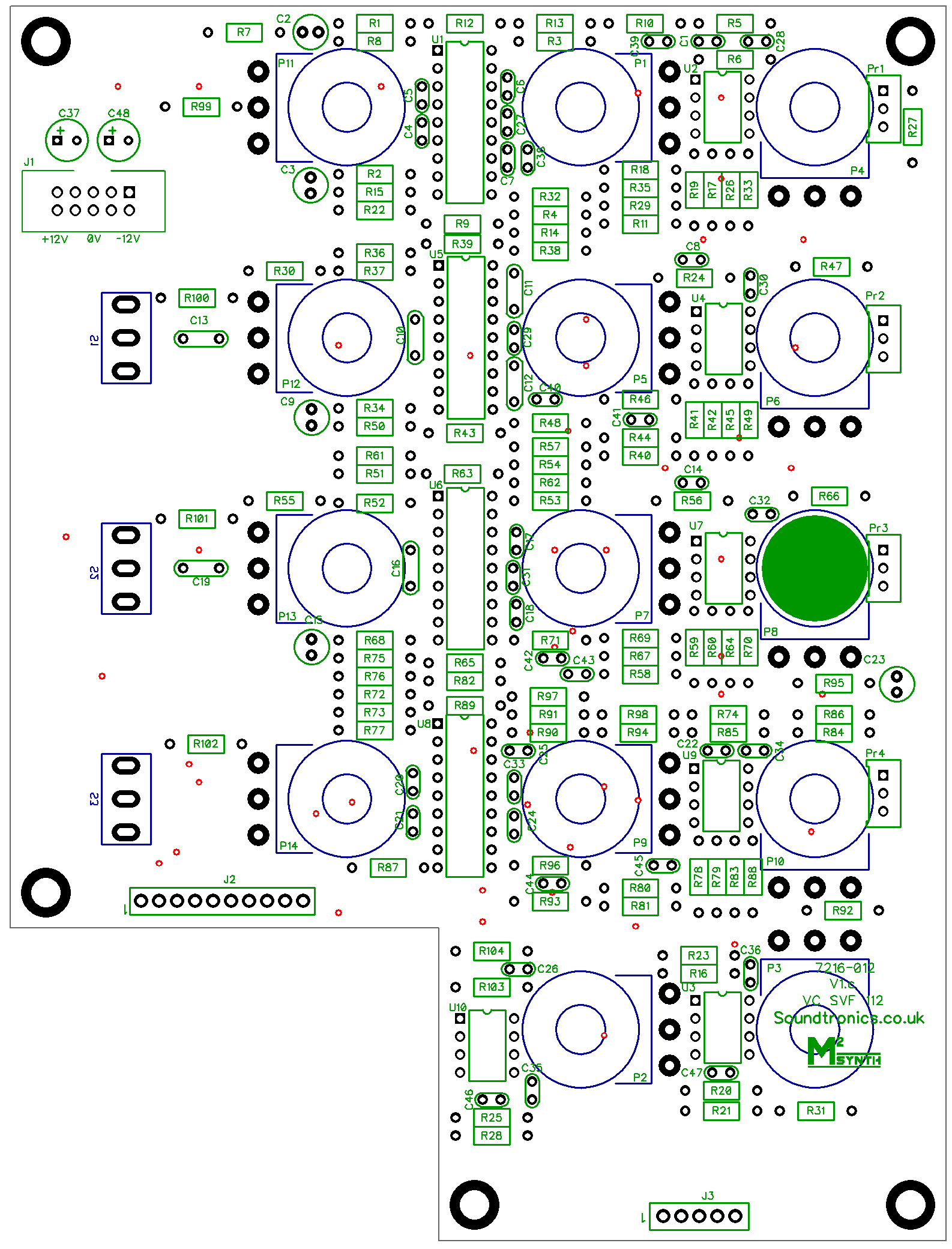
PCB Layout
There are no products in this section