

VCLFO 105 Build Guide
Assembly Instructions
The VCLFO 105 module has no particular build requirements not already covered in the ‘General Build Info' page.
Calibration
- Apply 0V to the V/Oct CV input
- Set fine pot to 50%
- Coarse pot to give approximately 10Hz pulse output.
- Use the fine pot to give exactly 10Hz
- Apply an accurate 5V to the V/Oct CV input
- Adjust trimmer P4 to give 320Hz
- Repeat steps 1-6 until applying a 5V CV gives 320Hz without needing to adjust P4
PCB Parts List
| Part Number | Quantity | Value | Name | RefDes |
| 7212-768 | 7 | 100n | 100n MLCC Capacitor | C1, C5, C6, C7, C9, C10, C17 |
| 7212-750 | 1 | 220n | 220n MLCC Capacitor | C2 |
| 7213-110 | 3 | 100u 25V | 100uF 25V Electrolytic | C3, C4, C8 |
| 7212-745 | 3 | 10n | 10n MLCC Capacitor | C11, C12, C13 |
| 7212-731 | 4 | 22p | 22p MLCC Capacitor | C14, C15, C18, C19 |
| 7212-704 | 1 | 47n Polyprop | 47n Polyprop | C16 |
| 7213-922 | 1 | LED - White | D1 | |
| 7212-486 | 2 | 1N914 | D2, D3 | |
| 7212-301 | 1 | Eurorack | Eurorack Power | J1 |
| 1208-010 | 1 | Flex Strip 10way | J2 | |
| 100k | Pot 100k Lin PCB Angle | P1, P2, P3 | ||
| 7212-857 | 1 | 10k | 10k Preset 25T 3296W | P4 |
| 7212-409 | 1 | 2N3904 | Q1 | |
| 7163-101 | 6 | 120k | 120k 0.25W 1% Metal Film Resistor | R1, R7, R15, R23, R28, R35 |
| 7163-089 | 3 | 39k | 39k 0.25W 1% Metal Film Resistor | R2, R25, R38 |
| 7163-055 | 2 | 1k5 | 1k5 0.25W 1% Metal Film Resistor | R3, R44 |
| 7163-099 | 4 | 100k | 100k 0.25W 1% Metal Film Resistor | R4, R9, R24, R27 |
| 7163-128 | 3 | 1M2 | 1M2 0.25W 1% Metal Film Resistor | R5, R6, R13 |
| 7163-075 | 4 | 10k | 10k 0.25W 1% Metal Film Resistor | R8, R17, R20, R30 |
| 7163-043 | 2 | 470R | 470R 0.25W 1% Metal Film Resistor | R10, R18 |
| 7163-051 | 5 | 1k | 1k 0.25W 1% Metal Film Resistor | R11, R22, R32, R39, R45 |
| 7163-082 | 2 | 20k | 20k 0.25W 1% Metal Film Resistor | R12, R21 |
| 7163-122 | 1 | 1M | 1M 0.25W 1% Metal Film Resistor | R14 |
| 7163-103 | 4 | 150k | 150k 0.25W 1% Metal Film Resistor | R16, R26, R37, R40 |
| 7163-070 | 2 | 6k2 | 6k2 0.25W 1% Metal Film Resistor | R19, R43 |
| 7163-084 | 1 | 24k | 24k 0.25W 1% Metal Film Resistor | R29 |
| 7163-057 | 1 | 1k8 | 1k8 0.25W 1% Metal Film Resistor | R31 |
| 7163-069 | 1 | 5k6 | 5k6 0.25W 1% Metal Film Resistor | R33 |
| 7163-058 | 1 | 2k | 2k 0.25W 1% Metal Film Resistor | R34 |
| 7163-110 | 2 | 300k | 300k 0.25W 1% Metal Film Resistor | R36, R41 |
| 7163-079 | 1 | 15k | 15k 0.25W 1% Metal Film Resistor | R42 |
| 7163-083 | 1 | 22k | 22k 0.25W 1% Metal Film Resistor | R46 |
| 2230-021 | 1 | -5V | 79L05 | U1 |
| 7212-544 | 1 | TL074 | U2 | |
| 7212-591 | 1 | AS3340 | U3 | |
| 7212-542 | 1 | TL072 | U4 |
*See below for MOTM or MU Potentiometers
Module Parts List
| Description | Reference | MOTM Qty | MU Qty |
| Pot Sticky Pads | 7210-188 | 3 | 3 |
| 10mm M4 Spacers | 7210-186 | 4 | 4 |
| LED Spacer | 7210-185 | 1 | 1 |
| M4 x 14 Cap Head Screws | 7210-187 | 4 | 4 |
| M3 x 8mm Stainless Panel Screws | 7216-151 | 4 | |
| 8-Pin IC Socket | 7212-331 | 1 | 1 |
| 14-Pin IC Socket | 7212-332 | 1 | 1 |
| 16-Pin IC Socket | 7212-333 | 1 | 1 |
| Power Lead | 7216-164 | 1 | |
| M²Synth MU / MOTM Voltage Regulator / Interface | 7216-170 | 1 | |
| MOTM Front Panel | 7216-505 | 1 | |
| MOTM Back Panel | 7216-805 | 1 | |
| MU Front and Back Panel | 7219-505 | 1 | |
| Main PCB | 7216-005 | 1 | 1 |
| Jack Socket PCB | 7215-724 | 1 | 1 |
| Jack Sockets | 7212-220 | 7 | 7 |
| B100k Pots Long Shaft Angled | 7300-820 | 3 | |
| B100k Pots Short Shaft Angled | 7300-821 | 3 | |
| KM20B Knobs | 7212-170 | 3 | |
| MU Knobs | 7212-169 | 3 | |
| Circuit Schematic | S-7216-005-c | 1 | 1 |
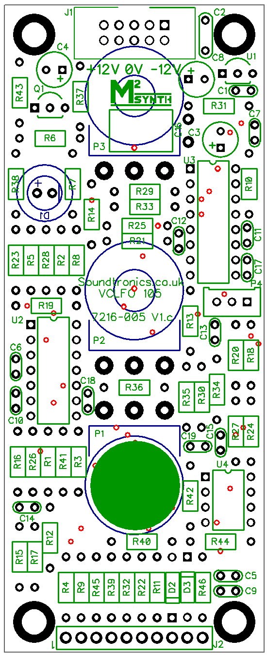
PCB Layout
There are no products in this section