

VCO 101 Build Guide
Assembly Instructions
The VCO 101 module has no particular build requirements not already covered in the ‘General Build Info' page.
Calibration
- Power up module and allow to ‘warm up’ for 15 minutes
- Measure mV across TP1 pins and adjust Pr5 ‘Null’ until as close to 0mV as possible
- Put the supplied red jumper on JP1. Adjust Pr1 ‘Set C5 with JP1’ until pulse output frequency is 523.25Hz. Then remove the red jumper, it is no longer required.
- Set coarse pot fully CCW, Fine pot fully CW
- Apply an accurate CV of 5V to the V/Oct input. Adjust Pr2 ‘Set C5 @ 5V CV’ until pulse output is 523.25Hz
- Reduce the CV from 5V to 0V. Adjust Pr4 ‘Scale’ until pulse output is 16.35Hz.
- Increase CV from 0V to 8V and adjust Pr3 ‘HF Trim’ until pulse output is 4186Hz
- That completes the calibration. The V/Octave tracking should be excellent from 16.35Hz through to 4186Hz and beyond subject to accurate CV calibration voltages and accurate frequency measurement. Aim for better than 0.05% accuracy from your test equipment for best results.
PCB Parts List
| Part Number | Quantity | Value | Name | RefDes |
| 7212-768 | 11 | 100n | 100n MLCC Capacitor | C1, C5, C6, C7, C9, C10, C11, C14, C25, C26, C28 |
| 7212-750 | 2 | 220n | 220n MLCC Capacitor | C2, C24 |
| 7213-110 | 4 | 100u 25V | 100uF 25V Electrolytic | C3, C4, C8, C27 |
| 7212-745 | 3 | 10n | 10n MLCC Capacitor | C12, C13, C15 |
| 7212-731 | 3 | 22p | 22p MLCC Capacitor | C16, C22, C23 |
| 7212-774 | 3 | 1n | 1n MLCC Capacitor | C17, C19, C21 |
| 2069-221 | 1 | 1n Polystyr | 1n Polystyrene | C18 |
| 7212-737 | 1 | 470p | 470p MLCC Capacitor | C20 |
| 7212-486 | 4 | 1N914 | D1, D2, D3, D4 | |
| 7212-301 | 1 | Eurorack | Eurorack Power | J1 |
| 1208-015 | 1 | Flex Strip 15way | J2 | |
| 1208-042 | 1 | 2-way Male Header | JP1 | |
| Pot 100k Lin PCB Angle* | P1, P2, P3, P4, P5, P6 | |||
| 7212-856 | 2 | 5k | 5k Preset 25T 3296W | Pr1, Pr5 |
| 7212-860 | 1 | 100k | 100k Preset 25T 3296W | Pr2 |
| 7212-858 | 1 | 20k | 20k Preset 25T 3296W | Pr3 |
| 7212-853 | 1 | 500R | 500R Preset 25T 3296W | Pr4 |
| 7163-086 | 1 | 30k | 30k 0.25W 1% Metal Film Resistor | R1 |
| 7163-101 | 6 | 120k | 120k 0.25W 1% Metal Film Resistor | R2, R11, R21, R31, R33, R40 |
| 7163-089 | 1 | 39k | 39k 0.25W 1% Metal Film Resistor | R3 |
| 7163-055 | 3 | 1k5 | 1k5 0.25W 1% Metal Film Resistor | R4, R34, R47 |
| 7163-099 | 5 | 100k | 100k 0.25W 1% Metal Film Resistor | R5, R9, R12, R13, R16 |
| 7163-084 | 1 | 24k | 24k 0.25W 1% Metal Film Resistor | R6 |
| 7163-128 | 2 | 1M2 | 1M2 0.25W 1% Metal Film Resistor | R7, R10 |
| 7163-106 | 1 | 200k | 200k 0.25W 1% Metal Film Resistor | R8 |
| 7163-075 | 6 | 10k | 10k 0.25W 1% Metal Film Resistor | R14, R24, R28, R29, R36, R38 |
| 7163-039 | 1 | 330R | 330R 0.25W 1% Metal Film Resistor | R15 |
| 7163-043 | 2 | 470R | 470R 0.25W 1% Metal Film Resistor | R17, R26 |
| 7163-081 | 3 | 18k | 18k 0.25W 1% Metal Film Resistor | R18, R35, R46 |
| 7163-051 | 5 | 1k | 1k 0.25W 1% Metal Film Resistor | R19, R30, R43, R48, R50 |
| 7163-122 | 3 | 1M | 1M 0.25W 1% Metal Film Resistor | R20, R22, R25 |
| 7163-103 | 3 | 150k | 150k 0.25W 1% Metal Film Resistor | R23, R32, R44 |
| 7163-070 | 1 | 6k2 | 6k2 0.25W 1% Metal Film Resistor | R27 |
| 7163-069 | 2 | 5k6 | 5k6 0.25W 1% Metal Film Resistor | R37, R39 |
| 7163-110 | 2 | 300k | 300k 0.25W 1% Metal Film Resistor | R41, R45 |
| 7163-058 | 1 | 2k | 2k 0.25W 1% Metal Film Resistor | R42 |
| 7163-083 | 1 | 22k | 22k 0.25W 1% Metal Film Resistor | R49 |
| 7212-250 | 1 | SPDT | S1 | |
| 1208-032 | 1 | 2-way Female Header | TP1 | |
| 2230-021 | 1 | -5V | 79L05 | U1 |
| 7212-544 | 1 | TL074 | U2 | |
| 7212-591 | 1 | AS3340 | U3 | |
| 2230-011 | 1 | 5V | 78L05 | U4 |
| 7212-509 | 1 | 4013B | U5 | |
| 7212-542 | 1 | TL072 | U6 |
*See below for MOTM or MU Potentiometers
Module Parts List
| Description | Reference | MOTM Qty | MU Qty |
| Pot Sticky Pads | 7210-188 | 6 | 6 |
| 10mm M4 Spacers | 7210-186 | 4 | 4 |
| M4 x 14 Cap Head Screws | 7210-187 | 4 | 4 |
| Toggle Switch Dress Nut | 7210-196 | 1 | 1 |
| M3 x 8mm Stainless Panel Screws | 7216-151 | 4 | |
| 8-Pin IC Socket | 7212-331 | 1 | 1 |
| 14-Pin IC Socket | 7212-332 | 2 | 2 |
| 16-Pin IC Socket | 7212-333 | 1 | 1 |
| Red Jumper | 7210-197 | 1 | 1 |
| Power Lead | 7216-164 | 1 | |
| M²Synth MU / MOTM Voltage Regulator / Interface | 7216-170 | 1 | |
| MOTM Front Panel | 7216-501 | 1 | |
| MOTM Back Panel | 7216-801 | 1 | |
| MU Front and Back Panel | 7219-501 | 1 | |
| Main PCB | 7216-001 | 1 | 1 |
| Jack Socket PCB | 7215-734 | 1 | 1 |
| Jack Sockets | 7212-220 | 6 | 6 |
| B100k Pots Long Shaft Angled | 7300-820 | 6 | |
| B100k Pots Short Shaft Angled | 7300-821 | 6 | |
| KM20B Knobs | 7212-170 | 6 | |
| MU Knobs | 7212-169 | 6 | |
| Circuit Schematic | S-7216-001 | 1 | 1 |
PCB Layout 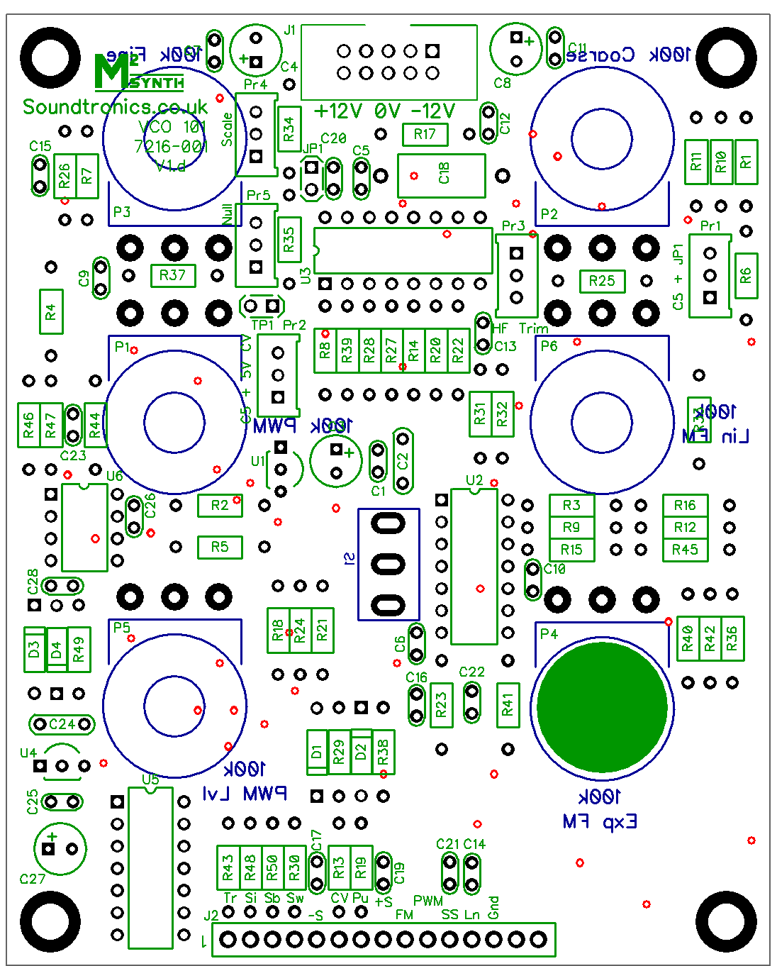
There are no products in this section