

General Build Info
General Guidance on a M²Synth Module Assembly
Component Identification
As the M²Synth module kits are not aimed at beginners, a basic knowledge of component identification and soldering is assumed.
Just to recap:
Resistors
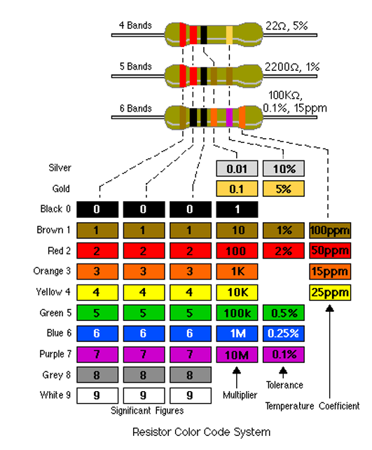
Most resistors will be of the 5-band type with a 1% tolerance (part number starts with 7163-). Some kits will have precision 0.1% tolerance resistors (part number starts with 2000-) and these will have the 6-band colour code. Where possible, we are moving to resistors with a 4-band code as these can be easier to identify. It is easy to get brown and red bands confused under certain lighting conditions so we always suggest double checking resistor values with a digital multimeter.
The chart below helps identify resistors included in the kit:
Capacitors
Electrolytic and Tantalum capacitors are straightforward because they have their value and voltage printed on their case. Most will also have an indication of the polarity (typically a -ve band running down one side). It is important that electrolytic capacitors are inserted into the PCB the correct way around as shown on the PCB and PCB overlay. Some kits have non-polarised electrolytic capacitors included which look just like an ‘ordinary’ electrolytic capacitor but there will not be any polarity markings on the body. These non-polarised capacitors can be inserted either way around.
Ceramic capacitors also have their value in pF written on in a short hand form. They use a 3-number code where the first two digits give the first part of the value, the third digit (on values of 100pF and greater) is the multiplier or number of zeros after the first two digits.
Examples: '102' means 10 with 2 zeros after which is 1000pF or 1nF. Another example is '10' and as no multiplier is included it is simply 10pF. Finally, '224' means 22 with 4 zeros after which is 220000pF. This last example requires further clarification, 1,000pF = 1nF so 220000pF = 220nF which is how it is likely to be referred to in the component lists. Some countries prefer to refer to capacitor values in differing ways, for example, 220nF may be identified as 0.22uF. Regardless, the value is the same but being familiar with the use of pF, nF and uF is encouraged.
Semiconductors
Integrated circuits (ICs), transistors and diodes have the manufacturers code written on them. For example, TL072 on Op Amp IC’s, 2N3904 on a transistor and 1N914 on a diode. Almost all semiconductor components will need inserting the correct way around. Look for the notch or dot on an IC (and the IC socket), the case shape of a transistor and the band on a diode showing the cathode. The PCB legend and PCB layout drawing show the correct orientation.
Potentiometers
We generally use 25-turn presets (trimmers) in our kits and these are used to set up / calibrate the module. It does not really matter which way around these are soldered in, the consequence is that you do not know whether to rotate the adjuster screw clockwise or counter-clockwise to for example increase the calibration voltage.
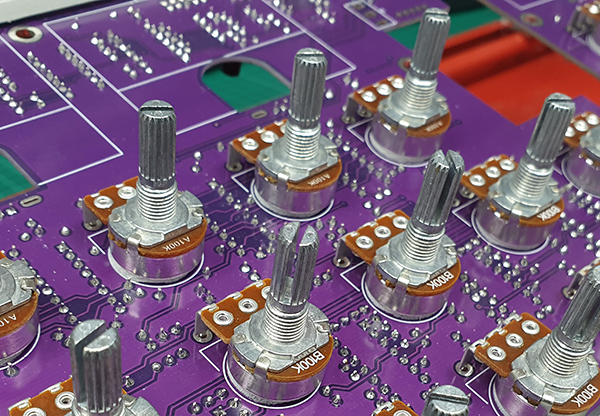
All M²Synth potentiometers are soldered direct to the PCB (on the opposite side to the electronic components) which eliminates the need for any panel wiring. Linear pots have the value prefixed with a letter 'B', log pots have the letter 'A'. For example, B100k is a 100k linear potentiometer and is by far the most commonly used pot in our modules. Some modules have a mix of 100k linear and 100k log pots so watch out for these.
Power Connectors
The power supply connector on a module is a 10-way box header which has a notch on one side. This notch must be aligned to the silk screen outline on the PCB.
LEDs
LEDs have one lead longer than the other and one side of the LED has a flat on it at its base. The PCB silk screen will show a ‘+’ symbol next to one pad, this is where the LED long lead (anode) is inserted. The cathode which is the short lead and adjacent to the flat on the LED body is inserted into the other pad that also has a representation of the flat printed onto the PCB.
LED Indicating Push Button Switches
A few modules have a tactile push button that also houses an integral green LED. These switches are soldered on the opposite side to the electronic components and a silk screen legend depicts the orientation. The LED switch has a ‘-‘ & a ‘+’ moulded into the underside of the switch where the ‘-‘ is the cathode. The cathode is also marked with a colour ink on the side of the switch body, the ink colour also represents the LED colour. At the time of writing this guide, all LED pushbuttons have green LEDs to signify their use as a gate signal. On the rear of the switch is a tiny round locating spigot that is best snipped off so as to allow the switch to sit better on the PCB.
Soldering
Overview
To provide the best possible performance, the M²Synth PCBs have ground planes on both sides of the PCB. Ground planes also suck away heat on pads that are directly connected to the ground plane. This means you should be using a good quality temperature-controlled soldering iron, especially if using a lead-free solder. We would recommend at least a 70W iron with a tip size of 2mm to 2.5mm. When soldering the pots, toggle switches etc, a larger tip may be necessary.
Common practice is to solder your components in ascending height order. This typically means soldering components in this sequence:
- Resistors and signal diodes
- Ceramic capacitors
- IC Sockets
- Tantalum capacitors
- Transistors
- Box headers
- Electrolytic capacitors
We would then recommend cleaning the flux deposits from the PCB prior to soldering the pots, switches and LEDs to the reverse side of the PCB. This is especially important if your solder is not of the’ No Clean’ type.
How you solder the components largely depends on what soldering aids you have in the way of a PCB holder jig. Where you solder one resistor at a time or like us have a jig that allows all resistors and diodes to be inserted before turning over to solder does not affect the outcome other than for how long the process will take.
We have developed over time some techniques that aid assembly of the pots, switches and jack sockets that we recommend you adopt.
Soldering Pots, Switches & LEDs
The pots used on the M²Synth modules are 16mm commercial pots with right angle pins. As all PCBs are spaced off 10mm from the rear of the panel, there is room to directly solder the pots to the underside of the PCB.
Stick a self-adhesive pad to each pot location
Remove the backing paper from the pad, tweezers are useful for this and place the respective pot in its correct location/ Most pots are B100k but not all! Do not solder at this time.
Place any toggle switches, 12x12mm tactile switches, rotary switches or LEDs in place. Some toggle switches may be centre off so ensure these are placed in the correct locations. Again, do not solder
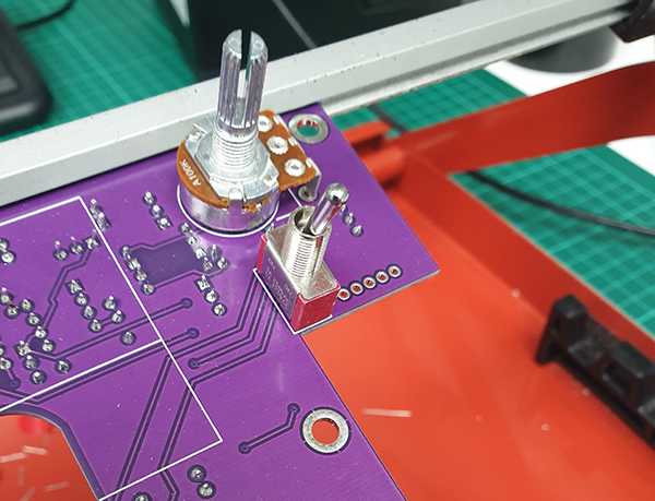
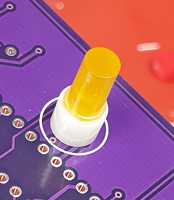
Note spacer under LED
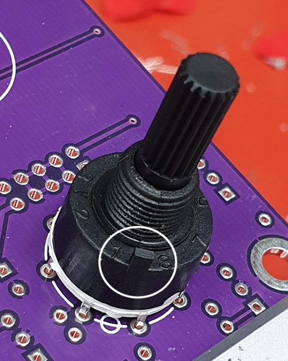
Snip off location lug
Place the aluminium (or acrylic for the MU version) back panel over the PCB while carefully aligning the switches etc into their respective holes in the panel. Carefully turn over the PCB and back panel together making sure they do not separate. Then fix the PCB to the back panel using the supplied spacers and screws.
Solder the pots, switches & LEDs. Make sure the toggle switches are lying flush on the aluminium. The LEDs + spacer are to be flush to the PCB by puling the LED upwards using one of its legs while soldering the other leg.
Remove the fixings to allow the PCB assembly to continue.
Soldering Jack Sockets
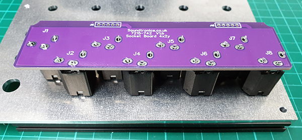
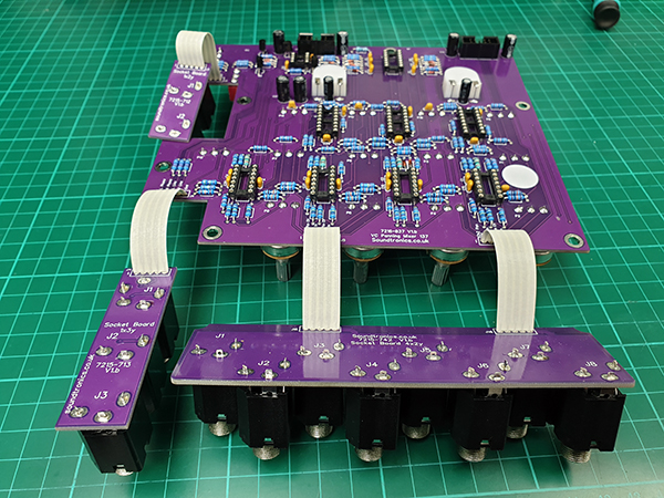
Identify the rear of the back panel (usually has the part number engraved on the rear face). The jack sockets are placed into the aluminium (or acrylic for the MU version) back panel with the panel sat on some props to provide clearance for the socket threads to poke through. Not all jack socket positions are used for every module so use the front panel as a reference to identify which jack sockets are used and in what position. Rotate each socket such that the chamfered corner is bottom left. Place the jack socket break out board over the socket pins, note the PCB should be orientated as per the photo below. Then solder the socket pins.
Soldering Header Cables
Soldering the header cable that joins the jack socket PCB to the main PCB requires particular attention as it is easy to get things the wrong way around.
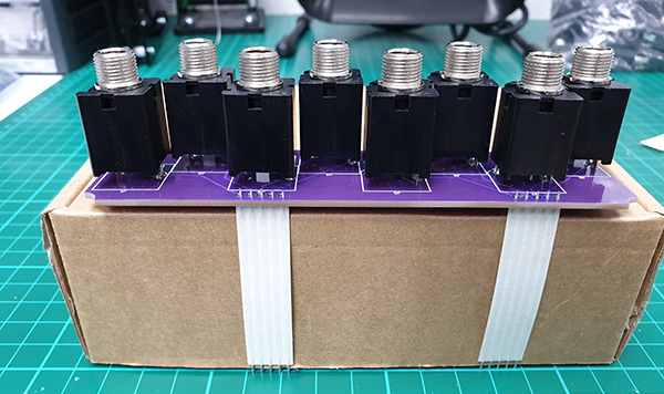
Solder the header cable(s) to the jack socket PCB. You may find it easier to place the PCB on a box of around 50mm high.
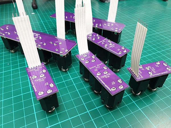
Some modules have multiple jack socket boards so prepare them all before moving on.
Soldering the jack socket PCB to the main PCB requires a bit of ingenuity. Really important is the orientation of the jack socket PCB in relation to the main PCB. The photo shows the correct way around.
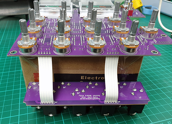
Once completed, you will have the PCBs joined together such that they will align with the panel.
Final Assembly & Testing
Our preferred assembly sequence for panels starts with mounting the main PCB to the rear of the aluminium (or acrylic for the MU version) back panel using the 10mm spacers and M4 cap head screws. Temporarily attaching the jack socket board(s) also to the back panel with one or 2 jack socket nuts. The front panel is not fitted at this time. No need to fit the pot or switch nuts at this time.
Insert the chips into the sockets in readiness for testing.
Refer to the specific testing section for the detailed calibration & testing requirements. As a rule, we first test each module from a current limited power supply and check the current drawn from each supply rail to ensure no underlying major assembly issues such as chips inserted incorrectly. Allow the module to reach operating temperature for around 10 minutes before commencing any calibration.
After testing and calibration. The front panel can be attached after first removing and nuts that have been fitted to the jack sockets or pots if any.
Place the front panel over the pots, re-insert the jack socket assembly and retain in position with a single jack socket washer and nut (barely finger tight). Now fit the remaining jack plugs nuts and washers, do not tighten at this stage. Fit the pot nuts (no washers) and the dress nuts for any toggle switches.
Tighten all nuts using a nut spinner, no need to over-tighten, just nip them up. Excessive force will cause the sockets or pots to twist and strain the solder connections. The dress nuts are different and require a specialist tool that we have not managed to source so we use a 3D printed tool. You can use a pair of fine nose pliers but be careful not to slip or you could end up damaging the panel face! Minimal force is needed so even finger tight can be enough.
The knobs are a push fit onto the splined shafts so simply rotate each pot fully CCW, alight the pointer mark on the knob to 0 on the scale and push on. You may find the splines to not permit an exact ‘0’ position so just make it as close as possible, they are never too far out.
Your latest module is now complete and ready for mounting into your Pod / rack.
There are no products in this section