

BP VCF 113 Build Guide
Assembly Instructions
The BP VCF 113 module has no particular build requirements not already covered in the ‘General Build Info' page.
Calibration
- Power up module and allow to ‘warm up’ for 10 minutes
- Connect a 440Hz sine wave @ 10V Pk-Pk to Signal input 1. Resonance to 0%, Signal 1 Level to 100%.
- Adjust cut-off to give maximum amplitude output using an oscilloscope.
- Adjust Pr1 to give a 10V Pk-Pk output.
- Remove the sine wave signal from input 1. Adjust resonance until self-oscillation occurs at approximate 10V pk-pk. Connect a frequency meter to the output.
- Adjust Cut-off to give 100Hz
- Apply a CV of 4V to the COF CV in 1 input
- Use Pr2 to calibrate at 1.6kHz (see note below)
- Repeat from step 5 until 4V gives 1.6kHz
Note: If the frequency is flat (<1.6kHz), use Pr2 and make the frequency lower (flatter), if above target frequency, use the trimmer to make the frequency even higher, this can be counter-intuitive. You will soon get the feel of how much to increase or decrease the frequency by.
PCB Parts List
| Part Number | Quantity | Value | Name | RefDes |
| 7213-110 | 2 | 100u | 100uF 25V Electrolytic | C1, C4 |
| 7212-768 | 4 | 100n | 100n MLCC Capacitor | C2, C3, C5, C6 |
| 7212-731 | 1 | 22p | 22p MLCC Capacitor | C7 |
| 7212-738 | 2 | 680p | 680p MLCC Capacitor | C8, C9 |
| 7212-737 | 2 | 470p | 470p MLCC Capacitor | C10, C11 |
| 7213-305 | 1 | 2u2 Non-Pol | 2u2 Non-Pol Electrolytic | C12 |
| 7212-301 | 1 | Eurorack | Eurorack Power | J1 |
| 1208-010 | 1 | Flex Strip 10way | J2 | |
| Pot 100k Lin PCB Angle* | P1, P2, P3, P4 | |||
| 7212-860 | 1 | 100k | 100k Preset 25T 3296W | Pr1 |
| 7212-859 | 1 | 50k | 50k Preset 25T 3296W | Pr2 |
| 7163-099 | 6 | 100k | 100k 0.25W 1% Metal Film Resistor | R1, R5, R6, R13, R20, R22 |
| 7163-090 | 1 | 43k | 43k 0.25W 1% Metal Film Resistor | R2 |
| 7163-097 | 5 | 82k | 82k 0.25W 1% Metal Film Resistor | R3, R4, R10, R11, R18 |
| 7163-095 | 2 | 68k | 68k 0.25W 1% Metal Film Resistor | R7, R12 |
| 7163-051 | 1 | 1k | 1k 0.25W 1% Metal Film Resistor | R8 |
| 7163-082 | 1 | 22k | 22k 0.25W 1% Metal Film Resistor | R9 |
| 7163-106 | 2 | 200k | 200k 0.25W 1% Metal Film Resistor | R14, R15 |
| 7163-101 | 4 | 120k | 120k 0.25W 1% Metal Film Resistor | R16, R19, R21, R25 |
| 7163-082 | 1 | 20k | 20k 0.25W 1% Metal Film Resistor | R17 |
| 7163-096 | 1 | 75k | 75k 0.25W 1% Metal Film Resistor | R23 |
| 7163-053 | 2 | 1k2 | 1k2 0.25W 1% Metal Film Resistor | R24, R26 |
| 7212-544 | 1 | TL074 | U1 | |
| 7212-589 | 1 | AS3320 | U2 |
*See below for MOTM or MU Potentiometers
Module Parts List
| Description | Reference | MOTM Qty | MU Qty |
| Pot Sticky Pads | 7210-188 | 4 | 4 |
| 10mm M4 Spacers | 7210-186 | 4 | 4 |
| M4 x 14 Cap Head Screws | 7210-187 | 4 | 4 |
| M3 x 8mm Stainless Panel Screws | 7216-151 | 4 | |
| 14-Pin IC Socket | 7212-332 | 1 | 1 |
| 18-Pin IC Socket | 7212-334 | 1 | 1 |
| Power Lead | 7216-164 | 1 | |
| M²Synth MU / MOTM Voltage Regulator / Interface | 7216-170 | 1 | |
| MOTM Front Panel | 7216-513 | 1 | |
| MOTM Back Panel | 7216-803 | 1 | |
| MU Front and Back Panel | 7219-513 | 1 | |
| Main PCB | 7216-013 | 1 | 1 |
| Jack Socket PCB | 7215-723 | 1 | 1 |
| Jack Sockets | 7212-220 | 6 | 6 |
| B100k Pots Long Shaft Angled | 7300-820 | 4 | |
| B100k Pots Short Shaft Angled | 7300-821 | 4 | |
| KM20B Knobs | 7212-170 | 4 | |
| MU Knobs | 7212-169 | 4 | |
| Circuit Schematic | S-7216-013-c | 1 | 1 |
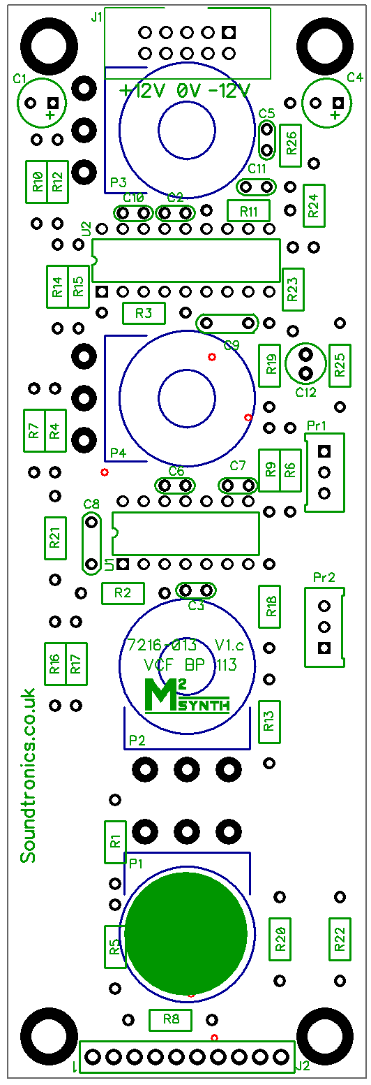
PCB Layout
There are no products in this section