

Ring Modulator 151 Build Guide
Assembly Instructions
The Ring Modulator 151 module has no particular build requirements not already covered in the ‘General Build Info' page except for:
U2 is a surface mount chip but can still be easily soldered by hand using a fine tipped soldering iron..
Calibration
This module requires calibration using Pr1 & Pr2 using a signal generator and an oscilloscope. Don’t have the test gear? Listen to the output and adjust for the lowest audible level where the text below refers to <30mV.
Apply a 1kHz, 10V P-P sine wave to input A with the toggle switch in the up position, Input level pot at 100% and Bypass at 0%. Adjust Pr2 until output is <30mV P-P.
As above but apply sine wave to input B, adjust Pr1 until output is <30mV.
To prove operation, apply a 1kHz 10V P-P sine wave to Input A, toggle switch down and check output is a sine wave at 2kHz (frequency doubling).
PCB Parts List
| Part Number | Quantity | Value | Name | RefDes |
| 7212-768 | 6 | 100n | 100n MLCC Capacitor | C1, C2, C6, C7, C10, C11 |
| 7212-770 | 3 | 470n | 470n MLCC Capacitor | C3, C4, C8 |
| 7212-731 | 1 | 22p | 22p MLCC Capacitor | C5 |
| 7213-110 | 3 | 100u | 100uF 25V Electrolytic | C9, C12, C13 |
| 7212-301 | 1 | Eurorack | Eurorack Power | J1 |
| 1208-005 | 1 | Flex Strip 5way | J2 | |
| Pot 100k Lin PCB Angle* | P1, P2, P3, P4 | |||
| 7212-853 | 2 | 500R | 500R Preset 25T 3296W | Pr1, Pr2 |
| 7163-099 | 3 | 100k | 100k 0.25W 1% Metal Film Resistor | R1, R2, R12 |
| 7163-079 | 4 | 15k | 15k 0.25W 1% Metal Film Resistor | R3, R14, R15, R17 |
| 7163-078 | 2 | 13k | 13k 0.25W 1% Metal Film Resistor | R4, R5 |
| 7163-105 | 2 | 180k | 180k 0.25W 1% Metal Film Resistor | R6, R8 |
| 7163-055 | 2 | 1k5 | 1k5 0.25W 1% Metal Film Resistor | R7, R16 |
| 7163-053 | 2 | 1k2 | 1k2 0.25W 1% Metal Film Resistor | R9, R10 |
| 7163-061 | 4 | 2k7 | 2k7 0.25W 1% Metal Film Resistor | R11, R13, R19, R22 |
| 7163-051 | 2 | 1k | 1k 0.25W 1% Metal Film Resistor | R18, R24 |
| 7163-071 | 2 | 6k8 | 6k8 0.25W 1% Metal Film Resistor | R20, R21 |
| 7163-067 | 1 | 4k7 | 4k7 0.25W 1% Metal Film Resistor | R23 |
| 7212-250 | 1 | SPDT | S1 | |
| 7212-542 | 2 | TL072 | U1, U3 | |
| 7212-502 | 1 | MC1496DR2G | U2 |
*See below for MOTM or MU Potentiometers
Module Parts List
| Description | Reference | MOTM Qty | MU Qty |
| Pot Sticky Pads | 7210-188 | 4 | 4 |
| 10mm M4 Spacers | 7210-186 | 4 | 4 |
| M4 x 14 Cap Head Screws | 7210-187 | 4 | 4 |
| M3 x 8mm Stainless Panel Screws | 7210-189 | 4 | 4 |
| 8-Pin IC Socket | 7212-331 | 2 | 2 |
| Power Lead | 7216-164 | 1 | |
| M²Synth MU / MOTM Voltage Regulator / Interface | 7216-170 | 1 | |
| MOTM Front Panel | 7216-551 | 1 | |
| MOTM Back Panel | 7216-851 | 1 | |
| MU Front and Back Panel | 7219-551 | 1 | |
| Main PCB | 7216-051 | 1 | 1 |
| Jack Socket PCB | 7215-722 | 1 | 1 |
| Jack Sockets | 7212-220 | 4 | 4 |
| B100k Pots Long Shaft Angled | 7300-820 | 4 | |
| B100k Pots Short Shaft Angled | 7300-821 | 4 | |
| KM20B Knobs | 7212-170 | 4 | |
| MU Knobs | 7212-169 | 4 | |
| Circuit Schematic | S-7216-051-b | 1 | 1. |
PCB Layout
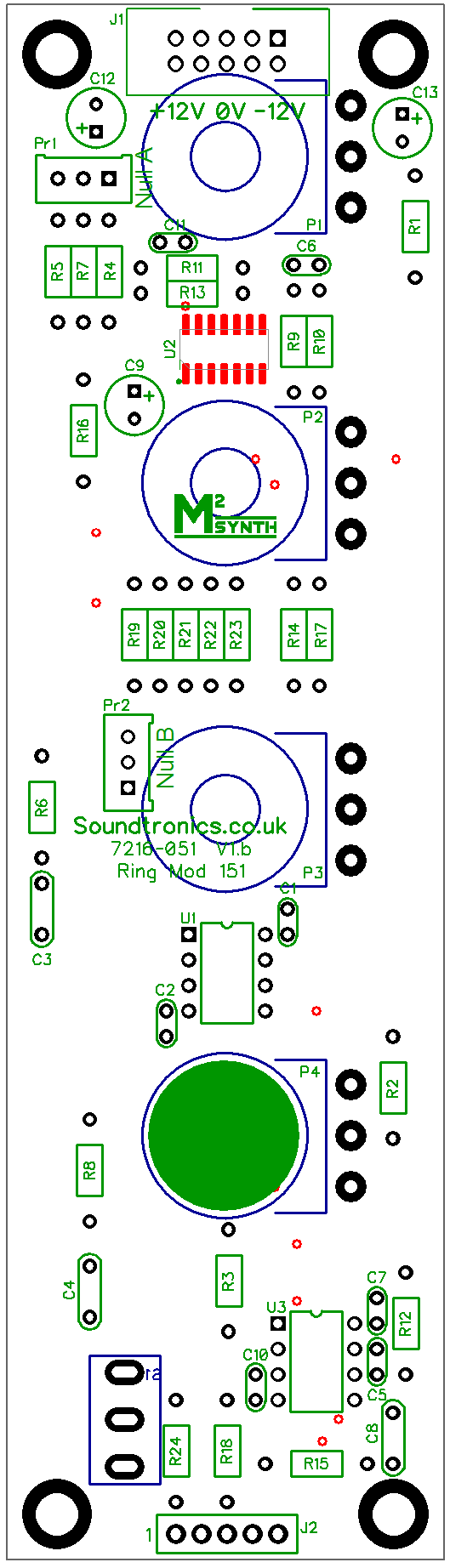
There are no products in this section