

VC Echo 160 Build Guide
Assembly Instructions
The VC Echo 160 module has no particular build requirements not already covered in the ‘General Build Info' page.
Calibration
- Power up module and allow to ‘warm up’ for 15 minutes
- Set the Delay pot to 100%
- Measure voltage at TP1 pins and adjust Pr1 until the voltage reads 50mV. This sets the maximum echo delay.
PCB Parts List
| Part Number | Quantity | Value | Name | RefDes |
| 7213-302 | 3 | 1u Non-Pol | 1u Non-Pol Electrolytic | C1, C3, C10 |
| 7213-110 | 3 | 100u | 100uF 25V Electrolytic | C2, C16, C25 |
| 7212-770 | 1 | 470n | 470n MLCC Capacitor | C4 |
| 7212-768 | 13 | 100n | 100n MLCC Capacitor | C5, C7, C9, C12, C13, C17, C18, C19, C20, C21, C22, C23, C24 |
| 7212-737 | 2 | 470p | 470p MLCC Capacitor | C6, C8 |
| 7212-745 | 1 | 10n | 10n MLCC Capacitor | C11 |
| 7213-109 | 1 | 47u | 47u 25V Electrolytic | C14 |
| 7212-763 | 1 | 4n7 | 4n7 MLCC Capacitor | C15 |
| 7212-731 | 1 | 22p | 22p MLCC Capacitor | C26 |
| 7212-771 | 1 | 1u | 1u MLCC Capacitor | C27 |
| 7212-486 | 10 | 1N914 | D1, D2, D3, D4, D5, D6, D7, D8, D9, D10 | |
| 7212-301 | 1 | Eurorack | Eurorack Power | J1 |
| 1208-010 | 1 | Flex Strip 10way | J2 | |
| Pot 100k Lin PCB Angle* | P1, P2, P3, P4, P5 | |||
| 7212-853 | 1 | 500R | 500R Preset 25T 3296W | Pr1 |
| 7212-409 | 1 | 2N3904 | Q1 | |
| 7163-099 | 19 | 100k | 100k 0.25W 1% Metal Film Resistor | R1, R4, R5, R13, R17, R18, R19, R26, R28, R31, R32, R38, R41, R42, R43, R44, R46, R47, R48 |
| 7163-082 | 10 | 20k | 20k 0.25W 1% Metal Film Resistor | R2, R6, R7, R10, R15, R20, R29, R37, R39, R45 |
| 7163-091 | 3 | 47k | 47k 0.25W 1% Metal Film Resistor | R3, R36, R51 |
| 7163-078 | 2 | 13k | 13k 0.25W 1% Metal Film Resistor | R8, R49 |
| 7163-101 | 5 | 120k | 120k 0.25W 1% Metal Film Resistor | R9, R24, R35, R50, R54 |
| 7163-069 | 2 | 5k6 | 5k6 0.25W 1% Metal Film Resistor | R11, R25 |
| 7163-075 | 3 | 10k | 10k 0.25W 1% Metal Film Resistor | R12, R21, R57 |
| 7163-067 | 4 | 4k7 | 4k7 0.25W 1% Metal Film Resistor | R14, R27, R40, R53 |
| 7163-051 | 4 | 1k | 1k 0.25W 1% Metal Film Resistor | R16, R30, R34, R55 |
| 7163-095 | 1 | 68k | 68k 0.25W 1% Metal Film Resistor | R22 |
| 7163-086 | 1 | 30k | 30k 0.25W 1% Metal Film Resistor | R23 |
| 7163-102 | 1 | 130k | 130k 0.25W 1% Metal Film Resistor | R33 |
| 7163-100 | 1 | 110k | 110k 0.25W 1% Metal Film Resistor | R52 |
| 7163-055 | 1 | 1k5 | 1k5 0.25W 1% Metal Film Resistor | R56 |
| 2230-011 | 1 | 5V | 78L05 | U1 |
| 7212-583 | 1 | PT2399 | U2 | |
| 7212-544 | 3 | TL074 | U3, U6, U7 | |
| 7212-599 | 1 | AS3364 | U4 | |
| 7212-542 | 1 | TL072 | U5 |
*See below for MOTM or MU Potentiometers
Module Parts List
| Description | Reference | MOTM Qty | MU Qty |
| Pot Sticky Pads | 7210-188 | 5 | 5 |
| 10mm M4 Spacers | 7210-186 | 4 | 4 |
| M4 x 14 Cap Head Screws | 7210-187 | 4 | 4 |
| M3 x 8mm Stainless Panel Screws | 7216-151 | 4 | |
| 8-Pin IC Socket | 7212-331 | 1 | 1 |
| 14-Pin IC Socket | 7212-332 | 3 | 3 |
| 16-Pin IC Socket | 7212-333 | 2 | 2 |
| Power Lead | 7216-164 | 1 | |
| M²Synth MU / MOTM Voltage Regulator / Interface | 7216-170 | 1 | |
| MOTM Front Panel | 7216-560 | 1 | |
| MOTM Back Panel | 7216-810 | 1 | |
| MU Front and Back Panel | 7219-560 | 1 | |
| Main PCB | 7216-060 | 1 | 1 |
| Jack Socket PCB | 7215-733 | 1 | 1 |
| Jack Sockets | 7212-220 | 8 | 8 |
| B100k Pots Long Shaft | 7300-820 | 5 | |
| B100k Pots Short Shaft | 7300-821 | 5 | |
| KM20B Knobs | 7212-170 | 5 | |
| MU Knobs | 7212-169 | 5 | |
| Circuit Schematic | S-7216-060-d | 1 | 1 |
PCB Layout
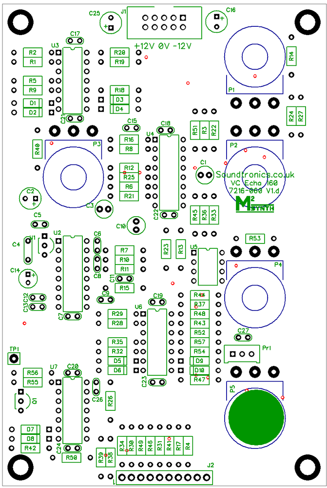
There are no products in this section