

Wave Folder 162 Build Guide
Assembly Instructions
The Wave Folder 162 module has no particular build requirements not already covered in the ‘General Build Info' page.
Calibration
- Apply a triangular waveform of +/-5V amplitude to the signal input
- Set the input level pot to 100% and the Initial Fold Level to 5%
- Monitor the output on a scope
- Adjust P3 until virtually no folding on the top of the waveform
- Adjust P1 until virtually no folding on the bottom of the waveform
PCB Parts List
| Part Number | Quantity | Value | Name | RefDes |
| 7213-110 | 2 | 100u | 100uF 25V Electrolytic | C1, C6 |
| 7212-768 | 6 | 100n | 100n MLCC Capacitor | C2, C3, C4, C5, C7, C8 |
| 7212-731 | 3 | 22p | 22p MLCC Capacitor | C9, C10, C11 |
| 7213-315 | 1 | 10u Non-Pol | 10u Non-Pol Electrolytic | C12 |
| 7212-486 | 6 | 1N914 | D1, D2, D3, D4, D5, D6 | |
| 7212-301 | 1 | Eurorack | Eurorack Power | J1 |
| 1208-005 | 1 | Flex Strip 5way | J2 | |
| 7212-858 | 1 | 20k | 20k Preset 25T 3296W | P1 |
| Pot 100k Lin PCB Angle* | P2, P4, P5 | |||
| 7212-859 | 1 | 50k | 50k Preset 25T 3296W | P3 |
| 7163-082 | 4 | 20k | 20k 0.25W 1% Metal Film Resistor | R1, R25, R33, R35 |
| 7163-098 | 1 | 91k | 91k 0.25W 1% Metal Film Resistor | R2 |
| 7163-099 | 19 | 100k | 100k 0.25W 1% Metal Film Resistor | R3, R4, R5, R6, R7, R10, R11, R12, R13, R14, R15, R17, R18, R24, R26, R28, R31, R32, R34 |
| 7163-091 | 1 | 47k | 47k 0.25W 1% Metal Film Resistor | R8 |
| 7163-101 | 2 | 120k | 120k 0.25W 1% Metal Film Resistor | R9, R20 |
| 7163-071 | 1 | 6k8 | 6k8 0.25W 1% Metal Film Resistor | R16 |
| 7163-057 | 1 | 1k8 | 1k8 0.25W 1% Metal Film Resistor | R19 |
| 7163-130 | 2 | 3M | 3M 0.25W 1% Metal Film Resistor | R21, R30 |
| 7163-051 | 2 | 1k | 1k 0.25W 1% Metal Film Resistor | R22, R27 |
| 7163-075 | 2 | 10k | 10k 0.25W 1% Metal Film Resistor | R23, R29 |
| 7212-250 | 3 | SPDT | S1, S2, S3 | |
| 7212-544 | 2 | TL074 | U1, U2 | |
| 7212-527 | 1 | 4016B | U3 | |
| 7212-521 | 1 | 40106B | U4 |
*See below for MOTM or MU Potentiometers
Module Parts List
| Description | Reference | MOTM Qty | MU Qty |
| Components Kit | 7216-262-1 | 1 | 1 |
| Accessories Pack including: | 7216-262-2 | 1 | 1 |
| Pot Sticky Pads | 7210-188 | 3 | 3 |
| 10mm M4 Spacers | 7210-186 | 4 | 4 |
| M4 x 14 Cap Head Screws | 7210-187 | 4 | 4 |
| M3 x 8mm Stainless Panel Screws | 7216-151 | 4 | |
| Toggle Switch Dress Nut | 7210-196 | 3 | 3 |
| 14-Pin IC Socket | 7212-332 | 4 | 4 |
| Power Lead | 7216-164 | 1 | |
| M²Synth MU / MOTM Voltage Regulator / Interface | 7216-170 | 1 | |
| MOTM Front Panel | 7216-562 | 1 | |
| MOTM Back Panel (1U4P4S) | 7216-862 | 1 | |
| MU Front and Back Panel | 7219-562 | 1 | |
| Main PCB | 7216-062 | 1 | 1 |
| Jack Socket PCB | 7215-722 | 1 | 1 |
| Jack Sockets | 7212-220 | 4 | 4 |
| B100k Pots Long Shaft Angled | 7300-820 | 3 | |
| B100k Pots Short Shaft Angled | 7300-821 | 3 | |
| KM20B Knobs | 7212-170 | 3 | |
| MU Knobs | 7212-169 | 3 | |
| Circuit Schematic | S-7216-062-b | 1 | 1 |
PCB Layout
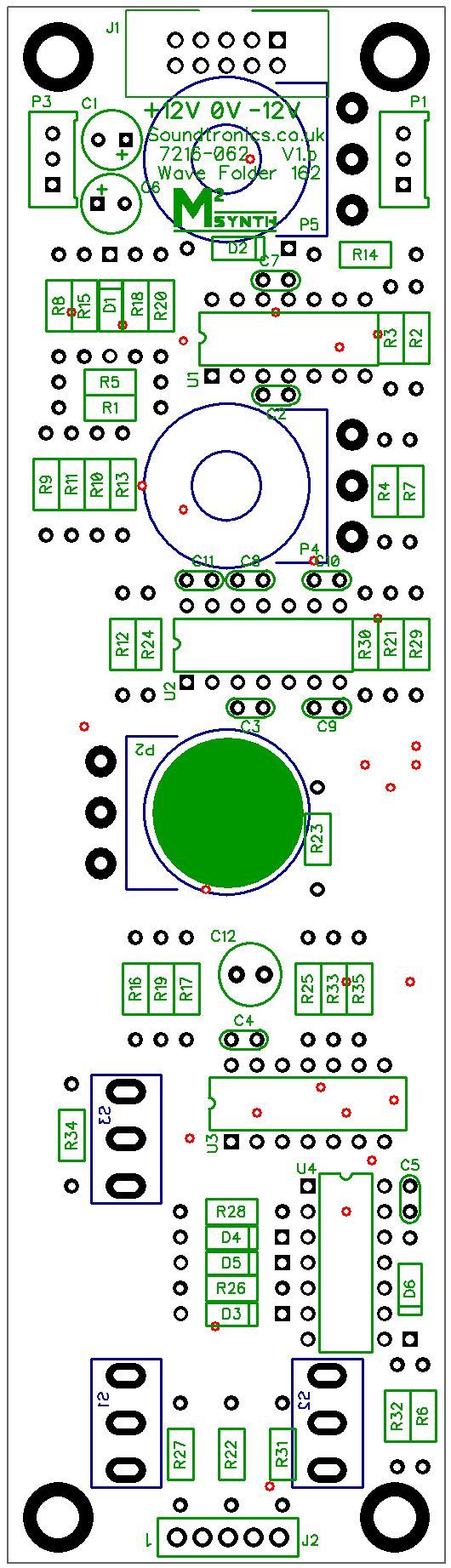
There are no products in this section