

About the ADSR 120
Features
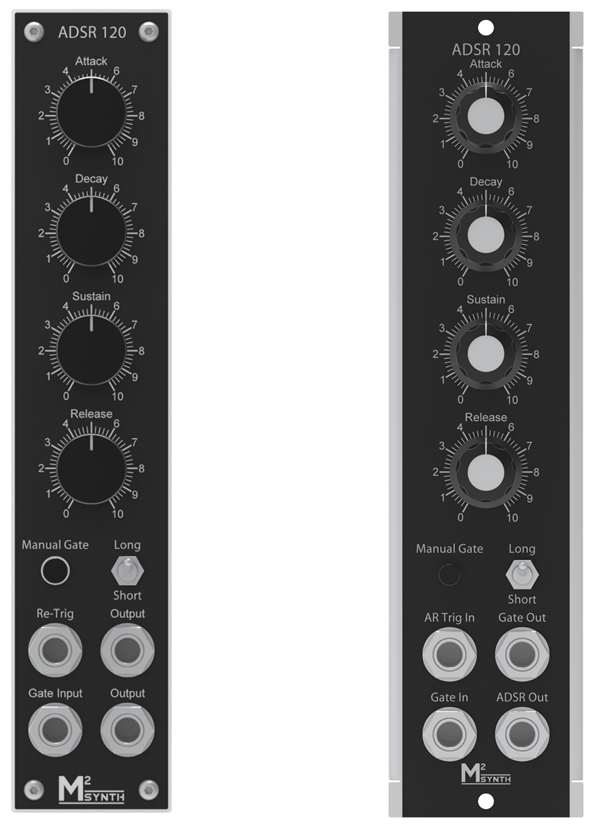
- Controls for Attack, Decay and Release envelope phases along with the Sustain level
- Time range selection switch x1 / x10
- Gate input for full ADSR output
- Manual gate button
- LED indicator of gate pulse
- AR Trig input for full AR envelope from a trigger pulse
- The AR Trig input can also be used for re-triggering the attack / decay phases whilst the gate input is active
- Gate output for cascading ADSR modules. Gate pulse width equal to the attack, decay and sustain periods (just the attack period when in AR trig mode).
Specification
- Supply voltage +/-12Vdc
- Supply current +20mA / -23mA
- Output level 0-10V
- Typical delay times
| Short Time Mode | |||
| Min | 50% | Max | |
| Attack | 3mS | 12mS | 1S |
| Decay | 6mS | 35mS | 3S |
| Release | 7mS | 40mS | 3S |
| ADSR | 16mS | 90mS | 7S |
| Long Time Mode | |||
| Min | 50% | Max | |
| Attack | 30mS | 120mS | 12S |
| Decay | 60mS | 350mS | 25S |
| Release | 70mS | 400mS | 30S |
| ADSR | 160mS | 900mS | 57S |
- Main PCB dimensions 43.5x154.85mm
There are no products in this section